3A-48 - 454 C.I.D. (7.4L) / 502 C.I.D. (8.2L)
90-823224--2 796
4. Measure the crankpin for out-of-round or taper
with a micrometer. If not within specifications, re-
place or recondition the crankshaft. If within
specifications and a new bearing is to be in-
stalled, measure the maximum diameter of the
crankpin to determine new bearing size required.
5. If within specifications, measure new or used
bearing clearances with gauging plastic or its
equivalent. If a bearing is being fitted to an
out-of-round crankpin, be sure to fit to the maxi-
mum diameter of the crankpin. If the bearing is
fitted to the minimum diameter, and the crankpin
is out of round .001 in., interference between the
bearing and crankpin will result in rapid bearing
failure.
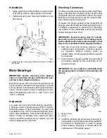
a. Place a piece of gauging plastic, the length of
the bearing (parallel to the crankshaft), on the
crankpin or bearing surface as shown. Posi-
tion the gauging plastic in the middle of the
bearing shell. (Bearings are eccentric and
false readings could occur if placed else-
where.)
72361
a
a - Gauging Plastic
b. Install the bearing in the connecting rod and
cap.
c. Install the bearing cap and evenly torque
nuts. Refer to “Specifications”.
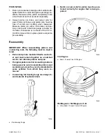
d. Remove the bearing cap and using the scale
on the gauging plastic envelope, measure the
gauging plastic width at the widest point as
shown.
IMPORTANT: Do not turn the crankshaft with the
gauging plastic installed.
72362
6. If the clearance exceeds specifications, select a
new, correct size bearing and measure the clear-
ance.
Be sure to check what size bearing is being re-
moved in order to determine proper replacement
size bearing. If clearance cannot be brought to
within specifications, the crankpin will have to be
ground undersize. If the crankpin is already at
maximum undersize, replace crankshaft.
7. Coat the bearing surface with oil, install the rod
cap and torque nuts
3/8 in. nuts
50 lb. ft. (68 N·m)
7/16 in. nuts
73 lb. ft. (99 N·m).


