3A-38 - 454 C.I.D. (7.4L) / 502 C.I.D. (8.2L)
90-823224--2 796
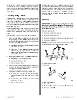
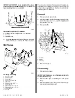
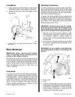
IMPORTANT: DO NOT move or disturb the orien-
tation of fitting on bottom of pan or incorrect oil
level readings may be obtained.
71308
c
a
b
Generation V MIE Engine Oil Pan
a - Factory Positioned Fitting For Tubes (Do Not Move)
b - Port Tube
c - Starboard Tube
6. Fill crankcase with required quantity of oil of spe-
cified viscosity. See Section 1B - “Maintenance.”
Oil Pump
72277
1
9
11
2
3
8
10
5
4
6
7
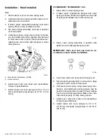
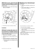
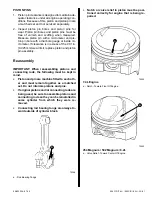
Oil Pump Assembly
1 - Extension Shaft
2 - Shaft Coupling
3 - Pump Body
4 - Drive Gear and Shaft
5 - Idler Gear
6 - Pickup Screen and Pipe
7 - Pump Cover
8 - Pressure Regulator Valve
9 - Pressure Regulator Spring
10- Retaining Pin
11- Screws
The oil pump consists of two gears and a pressure
regulator valve enclosed in a two-piece housing. Oil
pump is driven by distributor shaft which is driven by
a helical gear on camshaft.
Removal
1. Remove oil pan as outlined.
2. Remove gasket carefully as the one-piece gas-
ket for the oil pan may be reused if still pliable and
not cracked, torn, etc.
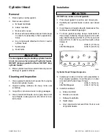
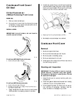
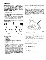
3. Remove baffle.
b
c
72545
a
a - Nuts (5)
b - Baffle
c - Oil Pump
4. Remove oil pump.
Disassembly
1. Remove pump cover.
IMPORTANT: Mark gear teeth for reassembly with
same teeth indexing.
2. Remove idler gear and drive gear from pump
body.
3. Remove retaining pin, spring, and pressure regu-
lator valve from pump cover.


