Mcr WIP type multi-blade fire dampers
6/17
MERCOR SA –
the Company reserves the right to make modifications and changes.
6.INSTALLATION OF THE FIRE DAMPER
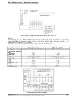
NOTICE
During the installation of a fire damper and while conducting finishing work, you should allow for
the possibility of later access to the fire damper and removal of the release and control
mechanism in order to carry out possible service work and technical inspections.
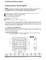
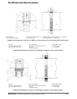
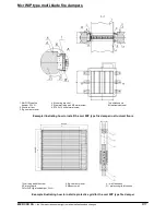
The mcr WIP fire dampers may be installed in the following space dividing elements (walls or structural floors):
masonry/concrete walls with a thickness of 120 mm brickwork
walls or concrete masonry unit walls with a thickness of 120 mm
walls made of boards with a thickness of 120 mm
structural floors with a thickness of 150 mm
Additionally, fire dampers may be installed:
outside walls
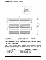
in larger fire damper systems/assemblies (multi fire damper sets)
The mcr WIP type fire dampers may also be installed in space dividing elements in buildings that have a lower fire-
resistance rating. In such cases, fire dampers will have a fire-resistance rating equal to that of a space dividing
element, with the condition of smoke leakage rating being satisfied. When installing a fire damper in a given type of
wall which is thinner than required, its thickness should be increased along the perimeter of the fire damper, e.g. by
installing an additional board or other building element.
6.1. PRE-INSTALLATION INSPECTION
Each fire damper is inspected by the manufacturer before packing and transport. Once the product has been
unpacked at the destination, visual inspection should be conducted to check for possible deformations of the
housing or fire damper transport damage.
6.2. INSTALLATION OPENING
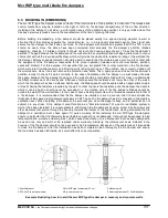
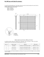
The minimum size of an installation opening necessary for correct installation of the mcr WIP type fire damper is:
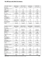
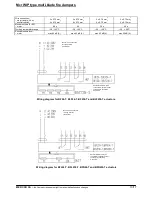
Bo = (A + Bz + 80) [mm]
Ho = (H + 180) [mm]
BF
BLF
BFL
BFN
BE
BLE
KW1
EXBF
C1 [mm]
385
335
335
385
385
335
335
460
A [mm]
125
125
125
125
125
125
165
175
Mixture


