background image

Mcr WIP type multi-blade fire dampers  


4/17 

MERCOR SA – 

the Company reserves the right to make modifications and changes. 


4.DESIGN AND OPERATING PRINCIPLE OF THE FIRE DAMPER 


Design


The mcr WIP type fire dampers consist of a housing with a rectangular cross section, movable partition made of an 
assembly of blades rotating on their axes as well as a release and control mechanism, which is started remotely or 
automatically  (after  a  thermal  release  has  been  actuated).  Fire  dampers’  housings  are  made  of  galvanised  steel 
sheet, stainless steel sheet or acid-proof sheet. An integral part of the housing is a flange made of a fire-resistant 
plate.  Each  damper  blade  is  made  of  galvanised  steel  sheet,  stainless  steel  sheet  or  acid-proof  sheet  with  a 
plasterboard  inside.  On  inside  of  the  housing,  along  the  partition  axis,  an  intumescent  seal  and  ventilation  seals 
have  been  installed.  The  partition’s  blades  rotate  on  their  axes  which  are  made  of  steel  pins.  On  the  blades, 
ventilation  seals  have  also  been  installed.  The  blades  are  connected  by  means  of  a  steel  slat  that  provides  the 
drive. 


Square and rectangular fire dampers have been equipped with flanged frames allowing to install them in ducts. In 
the case of a round duct, a square fire damper is manufactured and equipped with a circular flanged connection or 
a spigot is used. 


Operation


The operating principle and behaviour of the mcr WIP type fire dampers depends on the version and application:  


mcr WIP/S type fire dampers 

These  fire  dampers  remain  open  during  normal  operation.  They  are  closed  (safety  position)  in  the  following 
ways: 

  automatically – by actuation of the thermoelectric release 

  manually – by pressing the control button on the thermoelectric release 

  remotely – by actuation of the axial electric actuator with a return spring as the supply voltage disappear 


mcr WIP/V type fire dampers for fire ventilation systems 

These  fire  dampers  remain  closed  during  normal  operation.  They  are  opened  (safety  position)  in  the  following 
ways: 

  remotely  –  by  actuation  of  the  axial  electric  actuator  without  a  return  spring  as  the  supply  voltage  is 

appropriately applied to the actuator 


mcr WIP/M type fire dampers for mixed-mode fire ventilation systems 

Depending  on  the  function  they  serve,  these  fire  dampers  remain  either  closed  or  open  during  normal 
operation. They are opened/closed (safety position) in the following ways: 

  remotely  –  by  actuation  of  the  axial  electric  actuator  without  a  return  spring  as  the  supply  voltage  is 

appropriately applied to the actuator 


mcr WIP/T type transfer dampers 

These dampers remain open during normal operation. They are closed (safety position) in the following ways: 

  automatically – by actuation of the thermoelectric release 

  manually – by pressing the control button on the thermoelectric release 

  remotely – by actuation of the axial electric actuator with a return spring as the supply voltage 

disappears 


mcr WIP/G type pressure relief dampers 

These dampers remain open during normal operation. They are closed (safety position) in the following ways: 

  remotely – by actuation of the axial electric actuator with a return spring as the supply voltage 

disappears. The actuator does not have a thermoelectric release. 

It is possible to check manually the correct functioning of a fire damper with electric actuator for service purposes. 
To do this, use a special hex key which should be placed in the socket marked on the actuator. Then, by rotating 
the  hex  key,  the  fire  damper’s  partition  may  be  set  in  the  desired  position.  Bearing  in  mind  to  take  enough  care, 
rotate the hex key uniformly and slowly. Too fast and violent rotation may cause damage to the internal mechanism 
of the actuator or the power transmission system. 


NOTICE 
Never  try  to  open  or  close  a  fire  damper’s  partition  by  pulling  it  directly.  Such  attempts  may 
cause damage to the self-locking powertrain of a fire damper and this is not covered by warranty.
 

Summary of Contents for mcr WIP E120

Page 1: ...RTMENT Ul Grzegorza z Sanoka 2 80 408 Gda Phone 0 OPERATION AND MAINTENANCE MANUAL OMM mcr WIP type fire damper Rev WIP 15 06 15 3 FIRE VENTILATION SYSTEMS DEPARTMENT Ul Grzegorza z Sanoka 2 408 Gdańsk 58 341 42 45 FIRE VENTILATION SYSTEMS DEPARTMENT ...

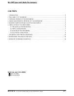
Page 2: ...AND OPERATING PRINCIPLE OF THE FIRE DAMPER 4 5 MANUFACTURER S DESIGNATION OF THE FIRE DAMPER 5 6 INSTALLATION OF THE FIRE DAMPER 6 6 1 PRE INSTALLATION INSPECTION 6 6 2 INSTALLATION OPENING 7 6 3 BUILDING IN THE FIRE DAMPER 7 6 4 ELECTRICAL CONNECTIONS 8 7 TRANSPORT AND STORAGE CONDITIONS 15 8 MAINTENANCE AND SERVICE REPAIRS 16 9 WARRANTY TERMS AND CONDITIONS 16 Markings used in the OMM Option ava...

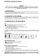
Page 3: ...WIP M type fire dampers for mixed mode fire ventilation systems the mcr WIP T type transfer dampers the WIP G type pressure relief dampers Fire dampers are not designed to work in ventilation systems where there is a risk of them coming into contact with dust laden air unless they have been covered by a special tailor made service and technical inspections programme Fire resistance The fire resist...

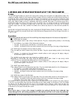
Page 4: ...s for fire ventilation systems These fire dampers remain closed during normal operation They are opened safety position in the following ways remotely by actuation of the axial electric actuator without a return spring as the supply voltage is appropriately applied to the actuator mcr WIP M type fire dampers for mixed mode fire ventilation systems Depending on the function they serve these fire da...

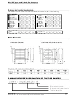
Page 5: ...BLE 230 S V M T G BFL 230 T S V M T G BFL 24 T S V M T G BFN 230 T S V M T G BFN 24 T S V M T G EXBF 24 S V M T G BF 24 T TL S V M T G BF 24 S V M T G Spring mechanism RST S V M T G RST KW1 S S V M T G RST KW1 24P S V M T G RST KW1 24I S V M T G Main dimensions a rectangular fire damper b fire damper with circular connections Dimensions of the release and control mechanism BF BLF BFL BFN BE BLE KW...

Page 6: ...e mcr WIP type fire dampers may also be installed in space dividing elements in buildings that have a lower fire resistance rating In such cases fire dampers will have a fire resistance rating equal to that of a space dividing element with the condition of smoke leakage rating being satisfied When installing a fire damper in a given type of wall which is thinner than required its thickness should ...

Page 7: ...be completely filled with A1 class non flammable certified mineral wool Its density and thickness should ensure fire resistance not lower than that of the wall in which the fire damper has been installed Additionally the filled space should be sealed with an appropriate mixture or mastic having fire resistance required by the wall In order to ensure fire resistance of a fire damper the depth to wh...

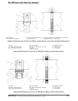
Page 8: ...alls 1 Air duct 2 ST4 2x16 sheet metal screw 3 Mcr WIP type fire damper W x H 4 E g cement mortar 5 Mineral wool with density of at least 80 kg m3 6 Heat resistant seal 7 Wall made of boards 8 ST5 5x38 screw X wall thickness Example illustrating how to install the mcr WIP type fire damper in walls made of boards 1 Air duct 2 ST4 2x16 sheet metal screw 3 Mcr WIP type fire damper W x H 4 E g cement ...

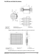
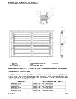
Page 9: ...plug with M6 metal screw 6 ST4 2x16 sheet metal screw 7 Ventilation duct 8 Heat resistant seal Example illustrating how to install the mcr WIP type fire damper in structural floors 1 Wall plug with M6 screw 2 Protective grid 3 Mcr WIP type fire damper W x H 4 E g cement mortar 5 Masonry wall X wall thickness G protective grid thickness Example illustrating how to install a protective grid for the ...

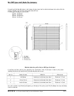
Page 10: ...frame 4 4 8 diameter rivet Modular protective grid for the mcr WIP type fire damper A modular protective grid may be supplied by the manufacturer of the fire damper or made by the person installing the product provided that the following requirements are met Item no Element name Material Dimensions 1 Grid blades Galvanised or stainless steel sheet Thickness 1 25 mm 2 Internal frame Galvanised or s...

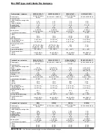
Page 11: ...to the electrical wiring system using the wiring system s cables if the fire damper is equipped with controls or other components that require such connection Shown below are the wiring diagrams and basic electrical data of the release and control mechanisms supplied together with the mcr WIP type fire dampers Actuator type Position of the fire damper s partition Belimo BFL series Belimo BFN serie...

Page 12: ... 24 V AC 220 240 V 50 60 Hz AC 24 V 50 60 Hz DC 24 V AC 220 240 50 60 Hz Power demand when putting the spring under tension when in standby 2 5 W 0 7 W 0 8 W 3 W 3 5 W 0 9 W 1 1 W 4 W 1 4 W 4 5 W 5 W 2 W 2 1 W Apparent power 4 VA 6 5 VA 6 VA 9 VA 10 VA Protection class III II III II IP rating IP 54 IP 54 IP 54 IP 54 auxiliary switch activation point degrees 2 x SPDT 3 0 5 A AC 250 V 2 x SPDT 3 0 5...

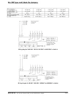
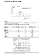
Page 13: ...ng temperature range 30 50 C 30 50 C 30 50 C 30 50 C Sound pressure level motor max 62 dB A max 62 dB A max 62 dB A max 55 dB A Wiring diagram for BF24 T BLF24 T BF230 T and BLF230 T actuators Wiring diagram for BFL24 T BFL230 T BFN24 T and BFN230 T actuators Notice 24 V connection through a safety transformer Several actuators may be connected in parallel Power consumption should be monitored Not...

Page 14: ... 0 N 000 Power supply 24 V AC 20 50 60 Hz 24 VDC 10 20 230 V AC 14 50 60 Hz Power demand when putting the spring under tension when in standby 7 W 2 W 8 W 3 W Apparent power 10 VA 12 5 VA IP rating IP 66 IP 66 Auxiliary switch activation point 2 x SPDT 6 A 3 max 250 V AC 5 80 2 x SPDT 6 A 3 max 250 V AC 5 80 Torque motor spring 18 Nm 12 Nm 18 Nm 12 Nm Movement time 90 C motor return spring 150 s 2...

Page 15: ...ring version the limit switches are installed on the mechanism itself Electrical connection is carried out by connecting the wires marked accordingly to the electrical wiring system The fusible release link is installed on the mechanism itself RST KW1 S RST KW1 24I RST KW1 24P 24 V 48 V DC 24 V 48 V DC 3 5 W 1 6 W 12 daN 12 daN 72 C 2 C NO NC changeover switch 5 A 230 V AC 3 87 2 tolerance 25 85 C...

Page 16: ...he product e g by removing thermal insulation suspended ceilings and disassembling other systems if they prevent free access to the product etc In the case of fire dampers installed in ducts it is recommended to make a service duct such as the mcr KRW type for instance Should fire dampers be installed on a roof access to the roof should be ensured by providing a ladder or lift For matters relating...

Page 17: ...l address MERCOR SA ul Grzegorza z Sanoka 2 80 408 Gdańsk Polska Poland 9 The buyer warranty holder shall use the products as instructed and carry out periodic technical inspections and maintenance in accordance with the rules set out in section SERVICE AND MAINTENANCE of this document 10 The warranty shall become void immediately in the following cases If the buyer warranty holder makes any modif...

Reviews: