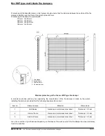
Mcr WIP type multi-blade fire dampers
11/17
MERCOR SA –
the Company reserves the right to make modifications and changes.
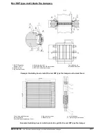
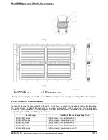
1. E.g. masonry wall
2. E.g. cement mortar
3. Mcr WIP fire damper, W x H
4. Mineral wool with thickness of at least
80 kg/m
3
5. 70 mm thick installation flat bar
6. ST8x16 screw
Example illustrating how to install the mcr WIP fire damper in an assembly consisting of four fire dampers
6.4. ELECTRICAL CONNECTIONS
Once a fire damper has been correctly installed, it is necessary to connect it to the electrical wiring system (using
the wiring system’s cables) if the fire damper is equipped with controls or other components that require such
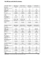
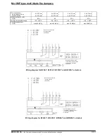
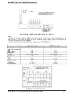
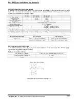
connection. Shown below are the wiring diagrams and basic electrical data of the release and control mechanisms
supplied together with the mcr WIP type fire dampers.
Actuator type
Position of the fire damper’s partition
- Belimo BFL series
- Belimo BFN series
Partition open – actuator indication 90˚
Partition closed – actuator indication 0˚
- Belimo BF series
- Belimo BLF series
Partition open – actuator indication 90˚
Partition closed – actuator indication 0˚
- Belimo BE series
- Belimo BLE series
Partition open – actuator indication 0˚
Partition closed – actuator indication 90˚


