


24
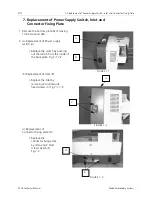
10. Replacement of Thread Breakage Sensor, S Board(unit), Upper Shaft Sensor and Solenoid.
EP 1B Technical Manual
Melco Embroidery Systems
10. Replacement of Thread Breakage Sensor, S Board(unit),
Upper Shaft Sensor and Solenoid.
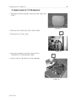
1. Replacement of Tread breakage sensor.
(a) Replacing Magnet sensor.
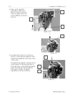
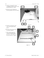
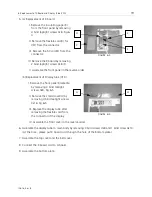
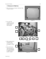
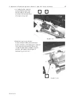
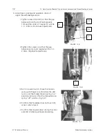
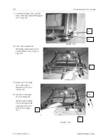
I. Remove 14 bind screws 4x5,and remove bottom
plate. Fig.10-1.
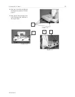
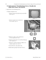
II.Remove magnet sensor connector(A)
from A board. Fig.10-2.
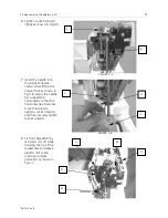
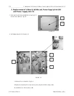
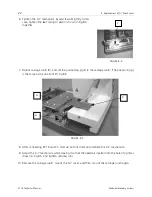
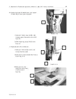
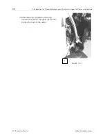
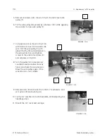
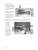
III. Remove 2 screws on nylon clips(B), and
remove magnet sensor cord.
IV.Remove 2 bind screws 3x4, and thread breakage
sensor plate (2) (C).
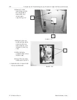
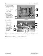
V.Remove a countersink head screw 2x8(D), and
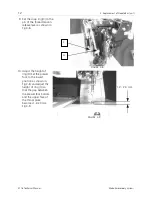
replace magnet sensor. Fig.10-5.
VI.Assemble them in the reverse order.
VII.After replacing, adjust the tension. Par.12-3.
FIGURE 10-1
FIGURE 10-2
A
G
FIGURE 10-3
B


