background image

11

12

13

14

15

16

SW1

SW2

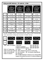
Fan on/off: 110-230VAC, 2.5A max., Fan VFS, PID valves, Hum., Dehum.: 0-10VDC. 0.5mA Not isolated
Control - Heat elements, Cool/Heat valves, Economizer: 110-230VAC, 0.3A max.

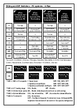
Wiring and DIP Switches – FC systems – 2-Pipe

2-Pipe,

1/2/3 Speeds fan

(1)

,

Cool/Heat valve,

Humidifier,

 Dehum/Reheat for 

Dehumidification

Fan high

Fan medium

(or Economizer

(5)

)

Fan low

Heat element

(2)

(2

nd

 stage heat)

Cool/Heat valve

(3)

(1

st

 stage heat)

Humidifier

2-Pipe,

1/2/3 Speeds fan

(1)

,

Cool/Heat valve,

Humidifier,

 Reheat for 

Dehumidification

Humidifier

Cool/Heat valve

(3)

(1

st

 stage heat)

2-Pipe,

Fan VFS,

Humidifier

 Reheat for 

Dehumidification

Cool/Heat valve

(3)

(1

st

 stage heat)

Fan VFS

2-Pipe,

1/2/3 Speeds fan

(1)

,

Cool/Heat PID,

Humidifier,

Reheat for 

Dehumidification

x

x

Fan high

Fan medium

(or Economizer

(5)

)

Fan low

Fan high

Fan medium

(or Economizer

(5)

)

Fan low

Heat element

(2)

(2

nd

 stage heat)

Heat element

(2)

(2

nd

 stage heat)

Heat element

(2)

(2

nd

 stage heat)

8

7

6

5

4

3

2

1

6

5

4

3

2

1

8

7

6

5

4

3

2

1

6

5

4

3

2

1

8

7

6

5

4

3

2

1

6

5

4

3

2

1

8

7

6

5

4

3

2

1

6

5

4

3

2

1

26

27

28

29

- 27 -

Cooll/Heat valve PID

(3)

(1

st

 stage heat)

Humidifier

AO1

X

AO2

X

X

Dehumidifier

(4)

(option - See SW2.3)

X

Humidifier

x

x

Economizer

(5)

(option - SW2.6 ON)

(1) 

SW1.1, SW1.2 = Fan speeds:  1 Speed (Low): 

SW1.1 ON, SW1.2 OFF

2 Speeds (Low and High): 

SW1.1 OFF, SW1.2 ON

3 Speeds (Low, Medium and High):  SW1.1 OFF, SW1.2 OFF

(2) 

SW1.4 = 2

nd

 heating stage:  ON – Enable, 

OFF – Disable

(3) 

SW1.5 = Chilled beam option  ON – Enable chilled beam (fan will not run with cooling)

(4) 

SW2.3 = Dehumidification:  ON – Use dehumidifier,  OFF – Use reheat for dehumidification

(5) 

SW2.6 = Terminal 12: 

ON – Economizer 
OFF – Fan Med. (3 Speeds) / Terminal not in use (1/2 Speeds/VFS)
Important: Economizer will not work in 3 fan speeds configuration

Summary of Contents for MTSCV/SUPER/PROG/HU/PIR

Page 1: ...MTSCV SUPER PROG HU PIR MTSCVW SUPER PROG HU PIR Owner s manual Technician Settings Rev 1 5 a...

Page 2: ...he and buttons Set buttons P08 Functionality of T1 terminals P09 Functionality of IN1 0 terminals P10 Window contact terminals IN1 0 polarity P11 Window contact delay time P12 Door switch terminals T1...

Page 3: ...gs P84 View T3 temperature sensor readings P85 Deice in cool cut in temperature P86 Deice in cool cut out temperature P87 Deice in heat time P88 Deice in heat break time P89 Deice in heat cut in tempe...

Page 4: ...to enter technician settings set point must be equal to 10 C 50 F Set point adjustment Temperature scale Modes Economizer indication Ambient Set point temperature display Ambient Humidity Press to tu...

Page 5: ...oint temperature for heating will appear on display Use the or buttons to adjust the set point for heating Notes The set point for cooling must be higher than the set point for heating For humidity se...

Page 6: ...n 3 speeds configuration Selecting Fan speeds for 2 and 3 fan speeds configuration Press the Mode button to switch between system modes Notes 1 During demand for cooling or heating the active mode wil...
Page 7: ...my set points Freeze Protection The Freeze protection feature will not allow the room temperature to drop below predefined cut in temperature Depending on which configuration the system is operating u...

Page 8: ...like External sensor Soft start in heat sensor Deicing in cool Door switch Key tag Whenever there is demand for cooling and the outdoor temperature conditions allow the operation of the economizer it...

Page 9: ...t temperatures system mode and fan speed Important Parameter P107 must not be equal to 0 in order to enable weekly program capabilities Changing P107 to 0 will disable all program capabilities and res...

Page 10: ...ime of program event Stop time of program event Set point s temperature Program event Mode US program type only Fan speed US program type only Exit programming procedure Program active indication Adju...

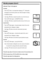
Page 11: ...xit the programming procedure At anytime during the programming procedure Press the button to exit and return to normal display any changed values will be saved Adjusting the time and day of the week...

Page 12: ...h Use the or buttons to adjust the start time minutes of the first event Stop time Press the button again the word Stop will appear on display The HOURS will flash Use the or buttons to adjust the sto...

Page 13: ...nt will appear on display Use the or buttons to select the mode default Auto mode Fan speed Press the button again the selected fan speed for the current programmed event will appear on display Use th...

Page 14: ...ING Risk of Electric Shock and Property Damage Disconnect power supply before making electrical connections The installation is to be performed by a qualified electrician WARNING The integrated circui...

Page 15: ...Installation Cont 15 2 1 5 3 6 5...

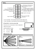
Page 16: ...r Deicing in cool sensor Door switch Supply 110 230VAC For T1 0 functionality refer to parameter P8 in the technician settings section For IN1 0 functionality refer to parameter P9 in the technician s...

Page 17: ...AC Configurations index Heat pump Fan speeds Fan VFS Economizer Humidifier Dehumidifier Reheat Dehumidify AC Configurations without humidification dehumidification AC Configurations with humidificatio...

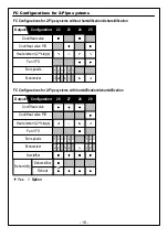
Page 18: ...without humidification dehumidification FC Configurations for 2 Pipe systems with humidification dehumidification Heat element 2nd stage Cool Heat valve Humidifier Cool Heat valve PID Fan VFS Fan spee...

Page 19: ...midification FC Configurations for 4 Pipe systems with humidification dehumidification 19 30 PID PID PID Cool valve PID Heat valve PID PID PID PID Configuration Outputs PID Yes Option 2 3 1 2 3 1 2 3...

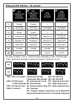
Page 20: ...SW1 SW2 8 7 6 5 4 3 2 1 6 5 4 3 2 1 8 7 6 5 4 3 2 1 6 5 4 3 2 1 8 7 6 5 4 3 2 1 6 5 4 3 2 1 Fan on off 110 230VAC 2 5A max Control Heat elements Heat pump Compressors Economizer 110 230VAC 0 3A max Wi...

Page 21: ...5 4 3 2 1 6 5 4 3 2 1 5 7 8 21 AO1 AO2 x x x Fan VFS x Fan VFS HP21 Fan VFS Heat pump 2 Heat element 2nd stage heat Compressor 3 8 7 6 5 4 3 2 1 6 5 4 3 2 1 6 x Fan VFS Economizer 5 option SW2 6 ON x...

Page 22: ...pressor 1 3 HP42 1 Speed fan Humidifier Dehum Reheat for Dehumidification Fan 1 speed Compressor 2 3 Heat pump 2 8 7 6 5 4 3 2 1 6 5 4 3 2 1 8 7 6 5 4 3 2 1 Heat element 2 4th stage heat Heat element...

Page 23: ...or Dehumidification Heat element 2 2nd stage heat Fan 1 speed Compressor 2 3 Compressor 1 3 HP32 1 Speed fan Economizer Humidifier Dehum Reheat for Dehumidification Fan 1 speed Heat pump 2 8 7 6 5 4 3...

Page 24: ...Economizer 5 Fan high Fan low Compressor 3 Heat pump 2 Humidifier x HP22 Fan VFS Humidifier 19 Compressor 1 3 Heat pump 2 Humidifier Fan VFS Compressor 2 3 HP21 Fan VFS Humidifier Reheat for Dehumidi...

Page 25: ...eat elements Heat pump Compressors Economizer 110 230VAC 0 3A max Wiring and DIP Switches AC systems 21 25 Compressor 3 AO1 AO2 Humidifier Fan VFS Heat element 1 2 1st stage heat x x Economizer 5 opti...

Page 26: ...lement 2 2nd stage heat Heat element 2 2nd stage heat Heat element 2 2nd stage heat 8 7 6 5 4 3 2 1 6 5 4 3 2 1 8 7 6 5 4 3 2 1 6 5 4 3 2 1 8 7 6 5 4 3 2 1 6 5 4 3 2 1 8 7 6 5 4 3 2 1 6 5 4 3 2 1 22 2...

Page 27: ...medium or Economizer 5 Fan low Fan high Fan medium or Economizer 5 Fan low Heat element 2 2nd stage heat Heat element 2 2nd stage heat Heat element 2 2nd stage heat 8 7 6 5 4 3 2 1 6 5 4 3 2 1 8 7 6...

Page 28: ...an high Fan medium or Economizer 5 Fan low Fan high Fan medium or Economizer 5 Fan low Floor heating 1st stage heat no fan Heat element 2 2nd stage heat Floor heating 1st stage heat no fan 8 7 6 5 4 3...

Page 29: ...4 3 2 1 8 7 6 5 4 3 2 1 6 5 4 3 2 1 6 5 4 3 2 1 8 7 6 5 4 3 2 1 34 35 36 37 29 AO1 AO2 x Heat valve 1st stage heat Cool valve PID 3 x x Heat element 2 2nd stage heat x Cool valve 3 Heat element 2 2nd...

Page 30: ...Pipe VFS Fan Cool valve PID Floor heating Floor heating 1st stage heat no fan x 39 Cool valve PID 3 Fan VFS 8 7 6 5 4 3 2 1 6 5 4 3 2 1 Heat valve 2nd stage heat x x Economizer 5 option SW2 6 ON 1 SW1...

Page 31: ...PID Humidifier Reheat for Dehumidification Fan high Fan medium or Economizer 5 Fan low Heat element 2 2nd stage heat x Cool valve 3 43 Heat valve PID 1st stage heat Humidifier 8 7 6 5 4 3 2 1 6 5 4 3...

Page 32: ...r 60 seconds the thermostat will automatically exit technician settings and return to normal display Use the or buttons to make adjustments when required P1 Offset for temperature readings calibration...

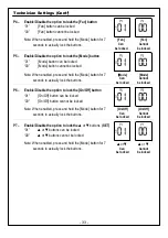
Page 33: ...ttons can be locked 00 or buttons cannot be locked or Can be locked or Cannot be locked P4 Enable Disable the option to lock the Fan button 01 Fan button can be locked 00 Fan button cannot be locked F...

Page 34: ...In heating mode the fan will not start before there is hot water in the coil Allow deicing operation of indoor coil in cooling In 2 Pipe system T2 will sense the water temperature in the pipe in order...

Page 35: ...Disable Auto change over mode 00 Disable Auto change over mode 01 Enable Auto change over mode Disable Auto mode Enable Auto mode P15 Occupancy sensor logic PIR 00 Thermostat turns off when unoccupie...

Page 36: ...s PIR ON delay minutes P19 PIR Occupancy sensor polarity 00 Normally open 01 Normally close PIR Normally open PIR Normally close P18 Door switch or key tag configuration 00 Switch On Off by door switc...

Page 37: ...int in heating P28 Off delay time between heating stages Range 0 600 seconds Default 1 second Off delay heating stages P27 On delay time on delay between heating stages Range 0 600 seconds Default 5 s...

Page 38: ...n ON delay in heating FC Only Range 0 120 seconds Default 0 seconds no delay P34 Fan OFF delay in heating Range 0 120 seconds Default 30 seconds Fan ON delay in cooling seconds Fan OFF delay in coolin...

Page 39: ...protection Enable freeze protection P35 Enable Disable Freeze protection 00 Disable Freeze protection 01 Enable Freeze protection F C Freeze protection cut out set point F C Note If enabled freeze pr...

Page 40: ...utton to reset the filter counter The display will change from 00 to 01 and back to 00 P42 Adjust filter alarm delay time counter hours Range 0 999 hours Default 0 hours 0 Disable View filter Counter...

Page 41: ...7 F P44 Soft start in heat cut out temperature FC Only The fan will stop if the temperature on T3 sensor drops below the cut out temperature Please refer to technician parameters P08 P09 Range 12 35 C...

Page 42: ...ON OFF Room Temp P45 P46 Cool differential band offset with cool differential band offset 0 Compressor Valve Set point Cool differential band P45 P46 Cool differential band offset with cool different...

Page 43: ...Technician Settings Cont ON OFF Room Temp P47 48 Heat differential band offset with heat differential band offset 0 Compressor Valve Set point Heat differential band P47 48 Heat differential band offs...

Page 44: ...0 10 C 0 20 F Default 2 C 4 F Shift between c F C F C Shift between heating F C 44 P49 Shift between Cool and Heat in Auto mode from cooling to heating Compressor Valve Cooling ON Temp Set point Cool...

Page 45: ...portional band FC Only Range 2 10 C 4 20 F Default 2 C 4 F P56 Heat proportional low limit FC Only Range 0 100 Default 0 Heat prop low limit P57 Heat proportional high limit FC Only Range 0 100 Defaul...

Page 46: ...s ON when the Cool or Heat valve reaches the Proportional ON percent P61 Fan turns OFF when the Cool or Heat valve drops below the Proportional OFF percent Fan 30 Proportional OFF percent Proportional...

Page 47: ...ing F C 0 10V fan speed from off closed to fully running 0 10V fan speed from off closed to fully running P67 Fan VFS Low speed percent in cooling Range 0 30 Default 20 P68 Fan VFS Medium speed percen...

Page 48: ...High 50 Fan VFS Med speed percent In cooling 90 Fan VFS High speed percent In cooling Fan VFS High speed diff 90 35 55 Fan VFS Medium speed diff 50 35 15 P74 VFS Medium speed differential display fro...

Page 49: ...0 P77 Fan VFS High limit in cooling Range 0 100 Default 100 P78 Fan VFS Low limit in heating Range 0 100 Default 0 P79 Fan VFS High limit in heating Range 0 100 Default 100 VFS low limit in cooling VF...

Page 50: ...reak time Deice in cool F C Deice in cool F C The indoor unit coil temperature in which deicing will stop The indoor unit coil temperature in which deicing will start The length of deicing procedure T...

Page 51: ...and one for heat One set point Two set points P98 Display set point only hide room temperature 00 Display both set point and room temperatures 01 Display only the set point temperature Hide room tempe...

Page 52: ...7 days with the different program for each day P108 Weekly program events per day 00 Two different events per day 01 Four different events per day P109 Weekly program event configuration 00 US Program...

Page 53: ...FC Only Range 0 100 Default 1 P119 Heat PID Kd FC Only Range 0 100 Default 1 P114 Cool PID Kp FC Only Range 0 100 Default 100 P115 Heat PID Kp FC Only Range 0 100 Default 100 Cool PID Kp Heat PID Kp...

Page 54: ...imum compressor ON time P161 Minimum compressor OFF time AC Only Range 0 20 minutes Default 13 minutes Minimum compressor OFF time 54 Economizer low limit temperature F C Enable internal PIR Disable i...

Page 55: ...Dehumidification break time in unoccupied mode Range 0 900 minutes Default 40 minutes Dehumidification cycle in unocc mode Dehumidification break in unocc mode Set point for reheat in unocc mode F C...

Page 56: ...on Range 0 100 RH Default 0 RH P197 Humidity set point Range 20 100 RH Default 45 RH Dead zone Hum Dehum Humidity set point P200 Restore defaults Press the button the display will change from 00 to 01...

Page 57: ...ar on display To enter MAC Address settings press and hold the button for 5 seconds Use the or buttons to change the MAC Address Set 0 for no communication Warning Do not use the same MAC address for...

Page 58: ...dication Deicer in heat indication Overheat in heat Overheat in cool Teconomizer sensor fault Economy by Built in External PIR Communication Economy by door switch Economy by Window contact Remote on...

Page 59: ...Notes 59...

Page 60: ...Tel 972 3 9626462 Fax 972 3 9626620 support meitavtec com www meitavtec com...

Reviews: