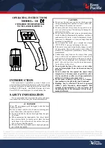
FEATURES
Clean, attractive style suits any decore
wall-mount design sits flush against wall
Includes both
o
C and
o
F control dials
SPECIFICATIONS
Electrical Ratings:
Electrical Ratings
0 - 2640 watts max. at
120 volts (22 amps)
0 - 4576/5280 watts at
208/240 volts (22 amps)
0 - 4986 watts at
277 volts (18 amps)
Sensing Element:
Bimetal
Temperature Operating Range:
5
o
- 35
o
C
41
o
-
95
o
F
Approvals:
Underwriters Laboratories Inc No.: E105830
Canadian Standards Association No.: LR30410
Mounting:
Mounts directly into a standard 2 x 4 inch vertical electrical
outlet box
SINGLE POLE THERMOSTAT INSTALLATION
WARNING
The installation of the thermostat must comply with the
applicable Local and/or National
Electrical Codes and utility requirements. This installation
should be entrusted to duly qualified personnel where
required by law.
WARNING
Ensure that all wiring connections to the thermostat are
correct and tight to prevent electrical shorts. Use the
appropriate wire to meet local and national electrical codes
for rated power consumption.
1. Disconnect power supply to prevent electrical shock or
product damage.
2. Run line voltage wiring to the thermostat location.
3. Do not remove the thermostat cover.
4. Connect the red LINE lead on the thermostat to the L1
line from the power supply panel.
5. Connect the black LOAD lead from the thermostat to the
line lead on the heater.
6. Connect the N Neutral (or L2) line to the remaining line
of the heater.
7. Secure the ground wire to the ground screw provided in
the outlet box.
8. Ensure that all connections are tight.
9. Insert wires into the outlet box taking care not to damage
the sensing device or wiring.
10.Remove the thermostat cover by grasping the cover by
the sides and pulling it away from the
thermostat base.
11.Mount the thermostat base into the wall box and secure
using the two supplied screws.
NOTE:
Do not over tighten mounting screws
12.Replace thermostat cover.
DOUBLE POLE THERMOSTAT INSTALLATION
WARNING
The installation of the thermostat must comply with the
applicable Local and/or National Electrical Codes and
utility requirements. This installation should be entrusted
to duly qualified personnel where required by law.
WARNING
Ensure that all wiring connections to the thermostat are
correct and tight to prevent electrical shorts. Use the
appropriate wire to meet local and national electrical codes
for rated power consumption.
1. Disconnect power supply to prevent electrical shock or
product damage.
2. Run line voltage wiring to the thermostat location.
3. Do not remove the thermostat cover.
4. Connect the black LOAD leads on the thermostat to the
leads on the heater.
5. Connect the red LINE leads on the thermostat to the line
leads from the power supply panel.
6. Ensure that all connections are tight.
7. Insert wires into the outlet box taking care not to damage
the sensing device or wiring.
8. Secure the ground wire to the ground screw provided in
the outlet box.
9. Remove the thermostat cover by grasping the cover by
the sides and pulling it away from the thermostat base.
10.Mount the thermostat into the wall box and secure
using the two supplied screws.
Dimplex Line Voltage Electric Heat Thermostat
NOTE:
Do not over tighten mounting screws
11.Replace thermostat cover.
OPERATION
To adjust the temperature to your individual requirements,
turn the thermostat control clockwise all the way to turn
on the heater. When the room reaches the desired
temperature, turn the thermostat knob counter clockwise
until you hear a click. Leave in this position to maintain
the room temperature at this setting. For additional heat,
turn clockwise until you hear the click again and the
heater will turn on.
For single pole models:-
Turning the knob fully counter
clockwise will set the temperature rating to 5
o
C (41
o
F).
For double pole models:-
Turning the knob fully counter
clockwise will disconnect the power to the heater.
INDEX PLATE REMOVAL
Using a small flat screwdriver or other suitable tool gently
pry up on one of the slots located on the index plate. To
install line up the index plate pins with the holes in the
thermostat knob and push until the index plate is flush
with the thermostat knob.
COVER
INDEX
PLATE
SCREW
BASE
OUTLET
BOX
HEATER
THERMOSTAT
L1 FROM
POWER
SUPPLY
NETURAL
FROM
POWER
SUPPLY
LINE RED
LOAD
BLACK
WIRE
CONNECTOR
HEATER
THERMOSTAT
LOAD
BLACK
WIRE
CONNECTOR
L1 FROM
POWER
SUPPLY
LOAD
BLACK
RED
LINE
RED
LINE
L2 FROM
POWER
SUPPLY
7207610100rev00