


12 Attachment: Technical Information
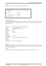
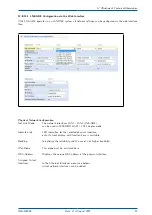
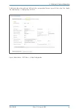
12.8.12.1 MRI Configuration via the Web Interface
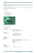
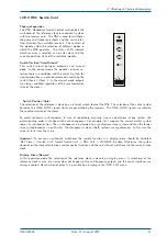
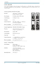
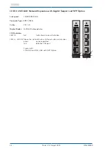
The MRI module is a card for fixed (none configurable) input signals (Time Code AM / DCLS, 10MHz and PPS).
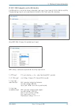
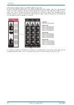
The provided input signals can be monitored and selected in the "Clock" menu after initializing.
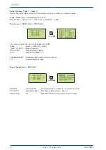
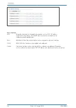
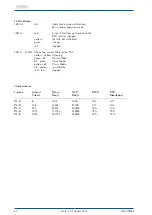
Menu MRS State: Displays the available input signals
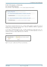
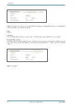
MRS settings: selection and prioritization of existing input sources
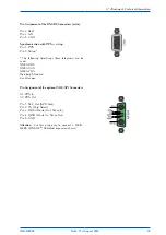
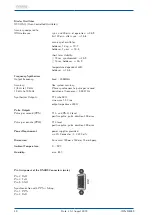
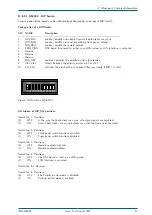
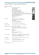
1 x PPS input:
TTL, pulse duration >= 5
µ
s, active high, female BNC connector
1 x 10 MHz input:
sine (1.5Vpp - 5Vpp) or TTL, female BNC connector
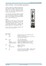
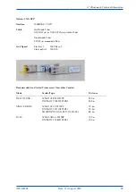
1 x Time Code
modulated input
BNC connector, isolated by transformer
Insulation voltage 3000 VDC
Input signal: 600mV to 8 V (Mark, peak-to-peak)
1 x Time Code
unmodulated input
BNC connector, isolated by opto-coupler
Insulation voltage: 3750 Vrms
Internal series resistor: 330 Ohm,
Max. input current: 25 mA
Diode forward voltage: 1.0 V...1.3 V
IMS-M4000
Date: 21st August 2019
49


