

M
ORE
A
BOUT
W
IRING
A-4
W
ir
in
g
S
te
p
M
o
to
rs
D
ir
ec
ti
o
n
P
u
ls
e
S
yn
ch
ro
n
iz
a
ti
o
n
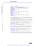
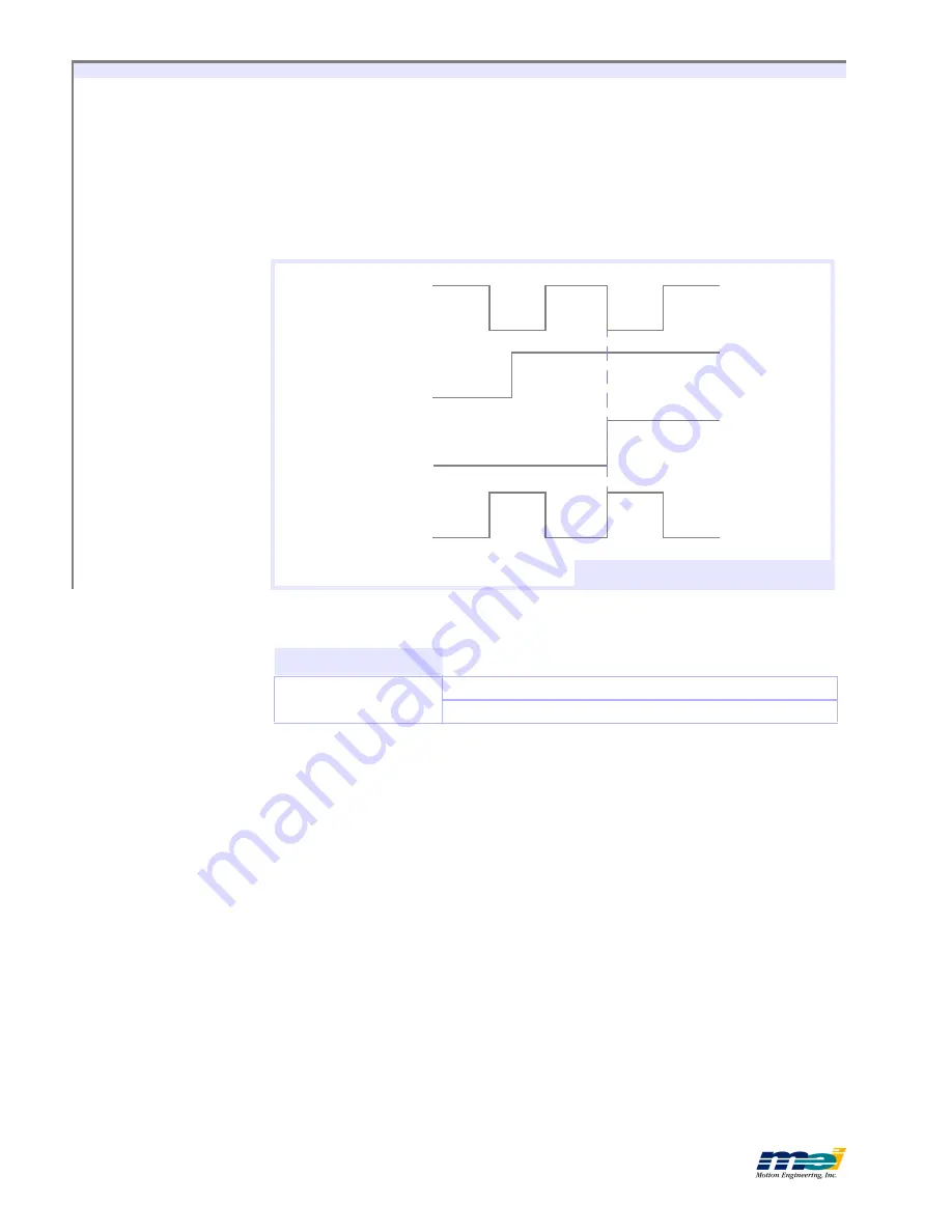
Direction Pulse Synchronization
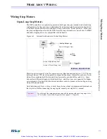
The DSP Series controllers synchronize the direction pulse with the falling edge of the pos-
itive step pulse output. When connected to the step drive properly, it ensures that a step pulse
and direction change will never occur at the same time.
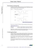
Figure A-2
Direction Pulse Synchronization
Most step drives count pulses on either the rising edge or falling edge of the step pulse input.
The Dir) should be connected to the direction input of the drive.
This guarantees
that the drive will never receive a direction change during a step pulse.
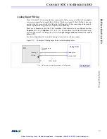
Closed-Loop Step Motors
DSP Series controllers can control step motors with encoder feedback. Closed-loop steps are
controlled by a PID algorithm running on the DSP in real time. The controllers accept TTL-
level (0V to +5V, 40mA max) encoder input from either differential or single-ended encod-
ers. Differential encoders are preferred due to their excellent noise immunity.
The connections for a single-ended encoder are identical to a differential encoder except that
no connections are made to channel A- and channel B-. The A- and B- lines are pulled up
internally to 2.5V.
Encoder signals are read in quadrature. Every line on the encoder will produce a rising edge
and a falling edge on channels A+ and B+, which is interpreted by the DSP controller as 4
encoder counts.
If the Driver triggers on the Then
falling edge
connect the controller’s
Step-
to the pulse input on the drive
rising edge
connect the controller’s
Step+
to the pulse input on the drive
Step+
direction
change
commanded
Dir+
Step-
D
IRECTION
P
ULSE
S
YNCHRONIZATION
Artisan Technology Group - Quality Instrumentation ... Guaranteed | (888) 88-SOURCE | www.artisantg.com