Technical Guide
Testing self-powered relays with SVERKER 900
Page 9(33)
When the operate time shown in the characteristic is tested, the inverse curve (or definite time curve) is tested.
This means to verify the
“operate time” of the overcurrent relay in different fault (current) conditions.
It is recommended to verify the operate time at least at current levels higher than 1,3 times the start value (1,3 x
Gs)
6
.
In this Technical Guide, the two test methods are combined in one test only. It is anyhow important to have in
mind these two fundamental concepts, related to the above 1) and 2):
a)
Verify “no trip” before the threshold. If overcurrent threshold I> is for example 1A, inject a current 10%
below, at 0,9 A and verify that the relay does not operate (trip).
If the threshold I>> is 5A, remember to inject a current 10% below it (or less), where you will observe
operation of I> but NOT the operation of I>>.
b) Verify the operate time at 1,3 times the threshold. If the overcurrent threshold I> is 1A, inject currents to
measure the operate time from 1,3 A. If the threshold I>> is 5 A, inject currents from 6,5 A.
The start value of 90% of the threshold is not
“written in the stones”, so feel free to use other margins to verify
the start values of the curves. Margins of 80% and 90% are reasonable.
Feel also free to test the operate times at values smaller than 1,3 times the threshold, but remember that in
case of discussions, the IEC 60255-151 requires to test the operate time at least at 1,3 times the start value, if
no other values are defined by relay manufacturer.
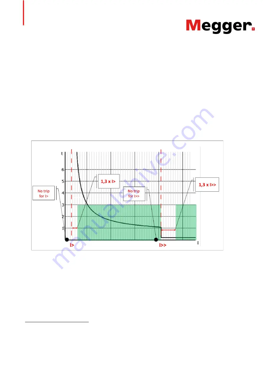
Figure 5 schematically represents the presented concepts.
Figure 5. Representations of the suitable zones for testing the operate time (in green), with fault current values
higher than the thresholds. Important is to test the “no-trip” for the thresholds, represented by the black fault
points 90% (or less) below the thresholds.
Finally, this document presents a good practical and rapid method for graphically verifying the tested time
characteristic for commissioning/maintenance purposes (par. 5.2.5).
The method is based on the idea that an error of the relay on the measurement of the current appear as an
error in the operate time. Without considering additional errors on the timers of the relay itself, it is possible to
graphically evaluate if the measured operate times are compatible with errors in current measurements of 10%
or maybe also 15%. If this method does not give clear indications, it is necessary to perform tests that are more
accurate before disqualifying the relay.
6 According to IEC 60255-151, the relay manufacturers have the right to declare the value of that coefficient. Some relays
may have different values than 1,3. This mea
ns that the relay user’s manual should be read. In general the value 1,3 (or
1,2) is a good value for a reasonable simplification.


