Technical Guide
Testing self-powered relays with SVERKER 900
Page 25(33)
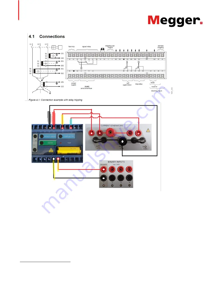
Figure 28. Schematic diagram representing the connections of the 3 current generators of SVERKER 900 to
WIP-1 and the operate contact. Also the connection diagram of WIP-1 is shown (from the WIP-
1 user’s manual
[4], Copyright SEG GmbH).
6.2.3. SVERKER 900 settings.
For testing the phase overcurrent protection function the instrument MTT [12] of pre-fault and fault and the
possibility to draw graphs of time curves is used
13
[13].
shows an extract of the SVERKER 900 user’s manual where the functionality of MTT in pre-fault and
fault instrument is described.
13 Note that not all SVERKER 900 are equipped with this functionality, please contact Megger for details.


