Electrical connection
13
3
Electrical connection
WARNING
Work on live equipment
The work can only be carried out safely while guaranteeing the protection
of the health of all those involved in the work by employing suitable
working procedures and using suitable protective equipment. For that
reason, the electrical connection of the device must absolutely conform to
the nationally applicable regulations for work on live equipment!
WARNING
Connection sequence
When connecting the device, the two blue connection cables should be
connected to the neutral conductor of the low voltage cable first. Not until
after that can the live phase conductors be connected. The conductors are
disconnected in reverse order: first disconnect the phase conductors, then
the neutral conductor.
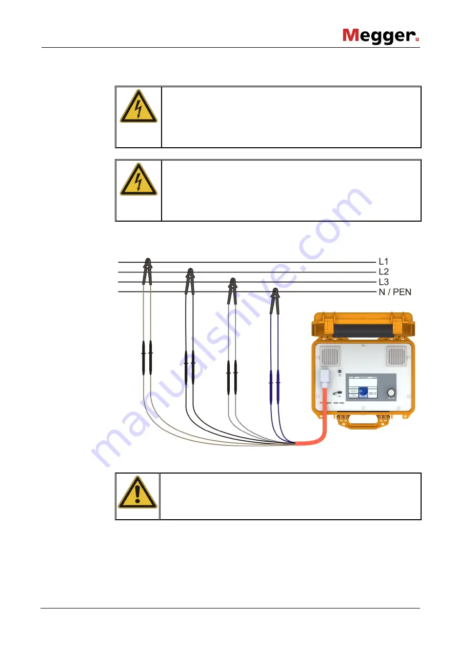
The following figure shows the simplified connection diagram for the NIM 1000:
CAUTION
The fused measurement cables are colour-coded (
brown = L1
,
black = L2,
grey = L3
,
blue = N
).
Only a measurement cable with a matching colourcode may ever be
connected to one and the same Kelvin clip!
Connection diagram
Summary of Contents for NIM 1000
Page 1: ...1 NIM 1000 Net Impedance Meter USER GUIDE Issue 04 06 2016 EN Article number 82941 ...
Page 2: ...2 ...
Page 6: ......


