EN
10010005001.01.
Abr
.19
6
R
Read these safety instructions carefully in addition to the instructions
for use, operation and maintenance.
This jack has been designed for use in the elevation of cars and lorries,
although it may also be used in other applications, provided that the
manufacturer’s instructions reflected in this manual are complied with.
Any other application, beyond the conditions established for use of
this jack will be considered inappropriate.
Handle the jack correctly and ensure that all parts are in good
condition prior to its use.
Only authorised persons should operate the jack having read carefully
and understood the contents of this manual.
Do not modify the jack in any way.
Non-compliance with these rules may result in injury or damage to the
user, the jack or the load to be lifted.
The manufacturer accepts no responsibility for the improper use of
the jack. manual
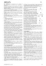
1. SAFETY INSTRUCTIONS
1.1. The load to be lifted should never exceed the rated capacity of
the jack.
1.2. The maximum stroke of the jack indicated on the label should
never be exceeded.
1.3. The jack should be supported on a solid, level and horizontal
surface which is well illuminated and free of obstructions. Never stand
the jack on a surface which may sink.
1.4. The air supply hose should not be worn and connections should be
in good condition. Keep the hose clean and away from heat, dirty areas
or sharp edges and do not bend it.
1.5. Ensure that there are no persons inside the vehicle to be lifted.
Switch off the engine and apply the brake. Ensure the vehicle
or element to be lifted against any type of sliding. Use chocks if
appropriate. (1). Do not enter the vehicle or start the engine whilst it is
supported on the jack or appropriate stands.
1.6. Position the jack under the manufacturer’s recommended lifting
point for the vehicle and ensure that it is not corroded, dirty or greasy.
This point should remain centred over the jack saddle. All off-centred
loads can slip and accidents may result.
1.7. During raising and lowering of the load, all precautions should be
taken to avoid movement of the vehicle load. Traffic may cause the
raised vehicle to rock during roadside use of the jack.
1.8. The jack should be positioned so as to avoid the need for the user
to introduce any part of his/her body underneath the vehicle. Never
work under a raised vehicle without previously supporting it with
mechanical stands (3) or other appropriate methods.
1.9. It is necessary for the operator to be able to observe the lifting
device and the load during all movements. In the presence of
dangerous conditions, such as movement of the vehicle, etc, the lifting
process must be interrupted.
1.10. Ensure that there are no persons or obstructions underneath the
vehicle prior to lowering.
1.11. As an additional safety measure against overload, the jack is
fitted with an overload valve set at the factory and which should not
be adjusted under any circumstances.
2. USE AND OPERATION
2.1. It is essential to install an air filter-lubricator control unit (D), which
is drained daily. Drain the boiler tank of the compressor daily. Poor air
quality damages essential parts of the jack.
2.2. Prior to connecting the air supply hose (8-9) to the network, check
that triggers A and B are not pressed. The section of the hose or air
network should not be inferior to that of the air intake connector. If
unusually long hoses are used, the air pressure needs to be increased.
2.3. Ensure that the same air pressure is maintained during operation.
Optimum performance of this jack is obtained with a pressure of 7-10
kg/cm² and a minimum air flow of 280 l/min.
2.4. Prior to using the jack, eliminate any air that may have accumulated
in the system. Using the numbers of the amplified pictures as a
reference, proceed as follows in models fitted with an operating lever:
- Position the lever (2) in the release valve (3) and turn once in an anti-
clockwise direction.
Introduce the lever into the lever support (5) and pump the jack several
times to ensure internal lubrication and the elimination of accumulated
air. Alternatively, press trigger A of the valve briefly.
- Position the lever in the release valve again and fully close it in a
clockwise direction.
- To eliminate air in models which are not fitted with an operating lever,
press triggers A and B of the valve simultaneously.
The jack is now ready for operation.
Important. Prior to lifting the load, ensure that
all of the aforementioned safety instructions are
followed.
2.5. The feed screw of the jack, if fitted,
complements its stroke. It is advisable not to fully
extend it.
2.6. For lifting in jacks equipped with a lever, close
the release valve (3) fully and press trigger A of
the air hose. The lifting operation may also be
performed by fully moving the lever (2) downwards
to obtain greater speed by using the full stroke
range of the piston. For jacks without a lever, lifting
is performed by pressing trigger A (red tube).
2.7. For lowering, slowly turn the release valve (3)
in an anti-clockwise direction using the lever (2),
ensuring that there are no persons or obstacles
under the vehicle to be lowered. The lowering
speed is controlled by the greater or lesser opening
of the release valve. For jacks without a lever, press
trigger B (blue tube) until lowering is completed.
During lowering, air is eliminated through a small
hole in the connector C. This air elimination is
normal. .
2.8. Should the jack be overloaded, it is fitted with
an overload valve which will prevent the vehicle from being lifted.
2.9. Our jack may be used in a horizontal position provided that the
pump is located on the lower side.
2.10. Never move the jack with the lever in the release valve as this
will cause damage.
2.11. Do not attempt to move the jack by pulling on the plastic air
supply tube.
3. MAINTENANCE
Important:
Both the maintenance and repair of the jack may only be
performed by qualified persons, who have sufficient knowledge of the
hydraulic systems used in these devices as a result of their training
and experience.
3.1. Keep the jack clean and lubricate all moving parts at regular
intervals (5), which must be clean and protected from aggressive
conditions at all times.
3.2. Only original spare parts should be used.
3.3. Prior to each use, check for bent, broken, cracked or loose parts
and solve the problem, if appropriate. If it is suspected that the jack
has been subjected to abnormal loads or has suffered any knocks,
withdraw it from service until the problem has been rectified.
3.4. If the oil level needs to be checked or refilled, with the piston
fully retracted, remove the filler plug and drain its contents into a
container. With the jack in a horizontal position, proceed to introduce
the necessary volume as indicated for each model in these instructions.
Make sure that no dirt enters with the new oil.
Following a period of prolonged intensive use, it is recommendable to
change the oil in order to extend the useful life of the jack.
Important: An excess of oil to the volume required may render the
jack inoperative.
3.5. Only use hydraulic oil, type HL or HM, with an ISO grade of
cinematic viscosity of 30 cST at 40º, or an Engler viscosity of 3 at 50ºC.
Extremely Important: Never use brake fluid.
3.6. When the jack is not in use, the screw, main piston and the pump
piston should be retracted to avoid corrosion.
Apply an anti-corrosion product to the piston, if appropriate.
Remove the handle from its position.
3.7. At the end of the useful life of the jack, drain off the oil and hand
it over to an authorised agent and dispose of the jack in accordance
with local regulations.
3.8. Both the repair kit, which exclusively contains the retainers and
joints of the jack and the spare part sets must be ordered using the
reference assigned in the table.
Summary of Contents for MGH-20
Page 3: ...R 10010005001 01 Abr 19 3...


