


24
VIII. Fine Tuning
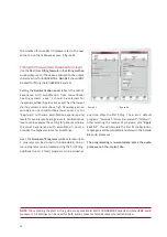
The Fine Tuning settings allow frequency specific gain
and compression as well as advanced speech in noise
adjustments to be made.
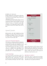
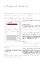
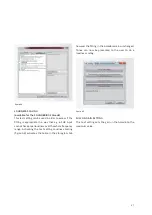
Frequency Shaping
The first tab in Fine Tuning allows the gain for each of
the 16 individual frequency bands to be adjusted
separately in incremental steps of 1 dB using a drag and
drop method (see figure 27).
If the mouse is moved over one of the controls, the
central frequency of the frequency band appears as well
as the current gain applied.
By marking several frequency bands with the mouse,
the gain in user-defined frequency areas can be changed
easily and quickly.
REMARK:
The number between 0 and 60 is interpreted in the
way that 60 is equivalent to the maximum amplification
on the specific frequency band and every 1 dB lower
means -1 dB below the maximum amplification. The
information value of this number is limited.
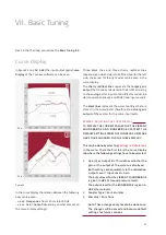
The exact values of the amplification applied depending
on frequency and input level can be taken from the
curve display.
REMARK:
Figure 27 shows that an increase of the overall gain
with the handle is not possible, as the control is
shown as non-active. This is interpreted in a way that
channels 11-13 are already set at maximum
amplification. To increase that overall volume of the
system the gain in the channels 11-13 has to be
reduced first, then the Master gain can be increased
again. Of course, this changes the frequency shaping
slightly.
The Maximum Power Output (MPO)
By setting this control, the maximum output of the
system can be limited. The MPO is a very fast compression
of signals represented in the last 2 dB of output of the
Amadé. This can be useful if the user complains that very
loud sounds are uncomfortable. The MPO can be set in
increments of 3 dB from 0 dB (no reduced output limit)
to -21 dB (output limit reduced by -21 dB).
Setting the MPO represents a reduction of the dynamic
range of the system and it is therefore suggested to do
this with caution.
Setting the MPO control to the utmost right position
sets the system into the Peak Clipping (PC) mode, the
MPO is deactivated. This means that the system uses
figure 27
Summary of Contents for SYMFIT 6.1
Page 1: ...1 Business Unit Vibrant Fitting Guide SYMFIT 6 1...
Page 2: ......
Page 4: ......
Page 39: ......


