45
Operating Manual
|
mechatron
ATC
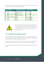
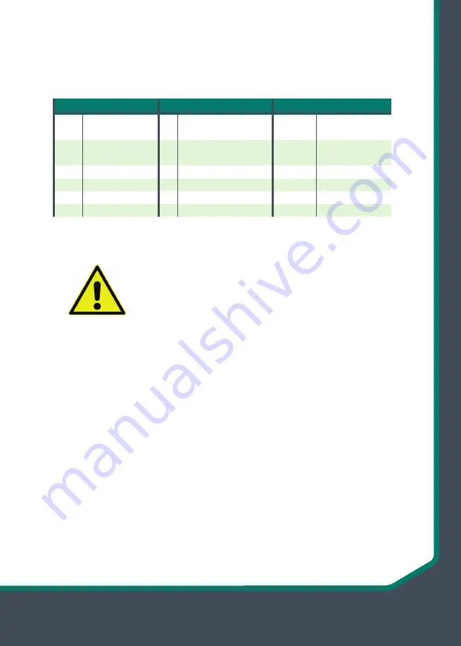
Motor spindles executed with breakout cable for wiring in the terminal box the cores are marked
separately and in different colors depending on the type.
Motor winding
Winding Protection PTC
Tool monitoring
U
See wire marking 1 1+2 same color,
S1 +24V brown
see wire marking
V
See wire marking
2 1+2 same color,
S1 Signal black
see wire marking
W
See wire marking
S1 0V
blue
PE
Green-yellow
S2
+24V
brown
S2
Signal
black
S2
0V
blue
It is pointed out that the electrical connection is in the responsi-
bility of the installer! In particular, the correct connection of the
protective conductor of the motor spindle and the subsequent PE
test should be carried out according to national regulations and
by qualified personnel!
7.4.3 Setting of the frequency inverter
The frequency inverter must be parameterized according to the above-mentioned precautions,
if this is not already being met by other safeguards. This applies particularly to the monitoring
tool, if this was not already covered by other engine controls.
The frequency inverter has to be set in V / f mode to the nominal current of the HF spindle. For
the curves for normal operation without boost please refer to the charts in the appendix.
Incorrect settings on the frequency inverter can lead to severe damage and increase the risk of
accident!
Summary of Contents for ATC Series
Page 28: ...28 Betriebsanleitung mechatron ATC ATC 12055 18 ATC 12065 24 ATC 12575 12 ...
Page 56: ...56 Operating Manual mechatron ATC ATC 12055 18 ATC 12065 24 ATC 12575 12 ...
Page 57: ...57 Betriebsanleitung mechatron ATC Notizen Notes ...
Page 58: ...58 Operating Manual mechatron ATC Notizen Notes ...

