


Technical
Manual
Room
Temperature
Controller
SCN
‐
RT1
MDT technologies GmbH •
51766 Engelskirchen • Papiermühle 1
Tel.: +49-2263-880 • Fax: +49-2263-4588 • [email protected] • www.mdt.de
30
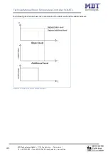
The
following
diagrams
shall
illustrate
the
connection
between
guiding
and
setpoint:
(Xsetpoint=new
setpoint;
Xbasic=basic
comfort
setpoint)
Illustration
18:
Example
Guiding
decrement
Illustration
19:
Example
Guiding
increment
The
communication
object
for
the
guiding
value
must
be
connected
to
the
external
measured
temperature.
Through
this
object,
the
guiding
becomes
the
reference
value
for
the
guiding
process.
The
following
chart
shows
the
relevant
communication
objects:
Number
Name
Length
Usage
20
Guiding
value
2
Byte
Receiving
of
the
reference
temperature
for
the
guiding
Chart
33:
Communication
object
guiding
Example
for
the
usage:
For
the
temperature
regulation
of
a
room,
the
setpoint
(22°C)
shall
be
increased
in
a
way
that
at
a
measured
outside
temperature
range
of
28°C
to
38°C,
the
difference
of
the
temperature
outside
and
inside
is
never
more
than
6K.
The
following
settings
must
be
done
at
the
controller:
Basics
Comfort
setpoint:
22°C
Guiding:
active
Guising
value
minimum:
28
°C
Guiding
value
maximum:
38°C
Setpoint
variation
at
maximum
guiding
value
:
10°C
If
the
temperature
outside
increase
to
value
of
32°C
now,
the
setpoint
will
be
increased
by
the
following
value:
X
=
10°C
*
[(32°C
‐
28°C)/(38°C–28°C)]
=
4°C
So
we
would
have
a
new
setpoint
of
22°C+4°C
=
26°C.
If
the
outside
temperature
reaches
the
adjusted
maximum
of
38°C,
the
setpoint
will
be
32°C
and
behave
this
value
even
if
the
temperature
would
continue
to
rise.