background image

WATER PIPING

GENERAL

A.

B.

C.

D.

E.

Piping practices vary considerably. In most cases C.

codes, local ordinances and established practices
govern the selection and installation of piping.
Local building and safety codes and ordinances
should be studied and complied with.

Shut off valves should be provided at the unit so
that normal servicing can be accomplished without
draining the system.

D.

It is recommended that temperature and pressure
indicators be installed at the inlet and outlet of

the shells to aid in the normal checking and ser-
vicing of the unit. Also, the installation of wire
mesh strainers at the pump suction will protect the
pump and shells from foreign matter.

A preliminary leak check of the water piping should
be made before filling the system.

Vibration eliminators are recommended in all lines

connected to the SEASONPAK air cooled water
chiller, to reduce vibration transmission.

CHILLED WATER PIPING

A.

B.

Each cooler is provided with the connections as
indicated in Figures 4 and 5, Page 7. Also, a  1 / 4 ”
NPT vent and 3/4” NPT drain are provided.

Design the piping so that it has a minimum number
of changes in elevation. Include manual or auto-
matic air vent valves at the high points of the

chilled water piping, so that air can be vented
from the water circuit. System pressures can be

maintained by using an expansion tank or a combi-

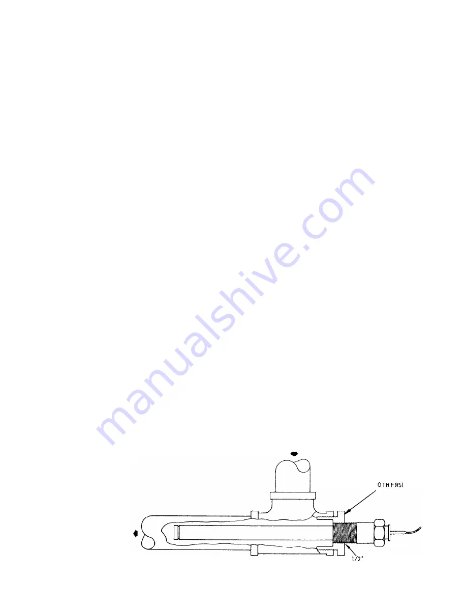
FIGURE 9

TO COOLER

nation pressure relief and reducing valve.

All chilled water piping should be insulated to

prevent the nuisance of water dripping from the
lines. If insulation is not of the self-contained
vapor barrier type, it should be covered with a

moisture seal. Do not insulate piping until it has
been tested for leaks and until all vent and drain
connections have been extended beyond the pro-
posed insulation thickness to make them accessible.

The chilled water  thermostat is mounted inside the
control center, and the control bulb, capillary tubing,

and control bulb immersion well are attached to
the unit with spring clips. The control bulb well
must be field inserted in the first tee installed in
the return water line as shown in Figure 9. The
bulb well is supplied with a l/2”  NPT male thread.
Carefully unsnap the well from the holding clips,
remove the retaining bushing and slowly remove
the bulb from the well. Install into piping as indi-
cated in Figure 9. When installing the bulb, care-
fully remove it f rom the well so as to not w i p e  off
the heat conducting compound supplied in the> well.
After installing the well, carefully insert t h e  bulb

and 

seal in with the excess compound. Insert t h e

retaining gasket and sealing hushing and clip or
tape the cap tube to the water  line. Care should be
taken not to break or kink the charged capillary
tubing. Sufficient cap tube length is provided for
bulb insertion up to 10 feet from the unit; h o w e v e r ,
it is recommended that the bulb well be placed  as
close to the cooler inlet as possible. Insulate over

thermostat well.

CAUTION: The thermostat hulh should not be e x -
posed to water temperatures above 125F since this
will damage the control.

THERMOSTAT WELL INSTALLATIONS

RETURN WATER

BUSHING

(BY 

 N.P.T.

Page 24

Summary of Contents for Seasonpak PAB Series

Page 1: ...15 AUGUST 1967 FORM 206034Y INSTALLATION AND MAINTENANCE DATA MODEL PAB AIR COOLED WATER CHILLER 7 1 2 THRU 60 TONS INC 13600 INDUSTRIAL PARK BLVD P O BOX 1551 MINNEAPOLIS MINNESOTA 55440 PHONE 377 97...

Page 2: ......

Page 3: ...Lability not strictly in accordan further warranty is h this policy except to the extent that such in writing and signed by an official of Mc Quay for additional consideration n in accordance with an...

Page 4: ...charge for the job requirements see Table 6 Pages 8 and 9 Charge for specific units can be obtained f rom the nameplatc The McQUAY line of air cooled water chillers is de signed for outdoor applicatio...

Page 5: ......

Page 6: ......

Page 7: ......

Page 8: ......

Page 9: ......

Page 10: ......

Page 11: ...s covering specific rcquircments CRANKCASE HEATERS The compressors are equipped with crankcase heaters Some models have heaters installed externally below the crankcase and others have heaters inserte...

Page 12: ......

Page 13: ......

Page 14: ......

Page 15: ......

Page 16: ......

Page 17: ...Check to see that the water temperature thermo stat is installed in the entering water line The L thermostat well is to be full of heat conducting compound and the bulb must be secured with the retain...

Page 18: ...graph E B Turn pumpdown switches S3 and S4 to auto posi tion Check liquid sight glass ahead of expansion valve for proper refrigerant charge C Observe operation for several minutes noting un usual sou...

Page 19: ...or at the unit an impedance relay is incorporated in the control circuit Basically this type of control is centered around a relay with a high impedance holding coil connected in series with the basic...

Page 20: ...low side of the system and its purpose is to shut down the D E compressor at the end of the pumpdown cycle It will open at 35 psig and automatically reset at approximately 60 psig The control can be c...

Page 21: ...een switches Do NOT make any adjustments other than the dial as this is a preset precision control TO CHANGE THE SET POINT 1 2 3 Loosen the setscrews on the collar below the hex nut see Fig 7 Turn the...

Page 22: ...checked as follows A Make up a depth gauge for inserting through the adjusting nut opening and long enough to hit the CONTROLS B C D E bottom of the bellows section as indicated in the diagrams A piec...

Page 23: ......

Page 24: ...t the nuisance of water dripping from the lines If insulation is not of the self contained vapor barrier type it should be covered with a moisture seal Do not insulate piping until it has been tested...

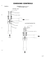
Page 25: ...on chamber on the motor end of the compressor Shut off valves E F G VIEW FROM END OF COOLER STRAIGHT PIPE EE D x D x 1 are never installed in these control lines The compressor is pre charged with suf...

Page 26: ...or of the moisture indicator button is an indication of the dryness of the system and is ex tremely important when the system has been ser v i c e d Immediately after the system h a s been opened for...

Page 27: ...nto heavy duty steel tube sheets and s c a l e d by a cast steel refrigerant head B The water connection nozzles which enter and leave the shell are on the same side of the unit No special attention i...

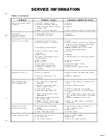
Page 28: ...e s s d D i s c h a r g e s h u t o f f v a l v e p a r t i a l l y d O p e n v a l v e c l o s e d L o w D i s c h a r g e P r e s s u r e a F a u l t y c o n d e n s e r t e m p e r a t u r e r e g...

Page 29: ...A d j u s t t h e r m a l e x p a n s i o n v a l v e C o m p r e s s o r l o s e s o i l a L o c k o f r e f r i g e r a n t b E x c e s s i v e c o m p r e s s i o n r i n g b l o w b y a C h e c k...

Page 30: ...ng parts refer to the model number and serial number of with an explanation of the malfunctions and a descrip the unit as stamped on the serial plate attached to the tion of the replacement parts requ...

Reviews: