background image

Page 4 of 12 / OM 897

Mounting

Find a suitable location for mounting your thermostat, 

preferably an interior wall centrally located within the 

conditioned space at about 5 feet above the floor. Try 

not to locate the thermostat in a place where it could 

be exposed to heat such as a warm air vent, or where it 

could be exposed to direct sunlight.

Wall-Mount

The T9000 back mounting plate provides six (6) 

mounting holes. The upper and lower holes on the vertical 

centerline will match up with screw positions of a standard 

electrical switchbox or dry-wall mounting ring.

Step One

Remove the back plate from the thermostat housing 

(Figure 2) and use it to mark locations for mounting 

holes. While operation of the thermostat is not affected 

by orientation, we recommend using a level across the 

top or side of the base plate to provide a professionally 

installed appearance.

Step Two

Drill  3/8"  holes  and  insert  drywall  fasteners  (#6 

screws recommended) and fasten the back plate to the 

wall.

Back Stand

Located on the back of the housing is a built-in, hinged 

stand support. This feature permits the thermostat to stand 

on a flat surface, such as a table or shelf, in the event that 

a permanent mounting to the wall is not desired. 

Buttons

Four  buttons  are  located  on  the  front  of  the 

T9000.

Figure 4.


Fan 

Up 

Down  Heat/Cool

These buttons are used in adjusting fan operation, 

changing  the  set  point  temperature  up  or  down,  and 

changing  the  operating  mode  of  the  thermostat.  See 

Figure 1 & 11 for front view of the thermostat and button 

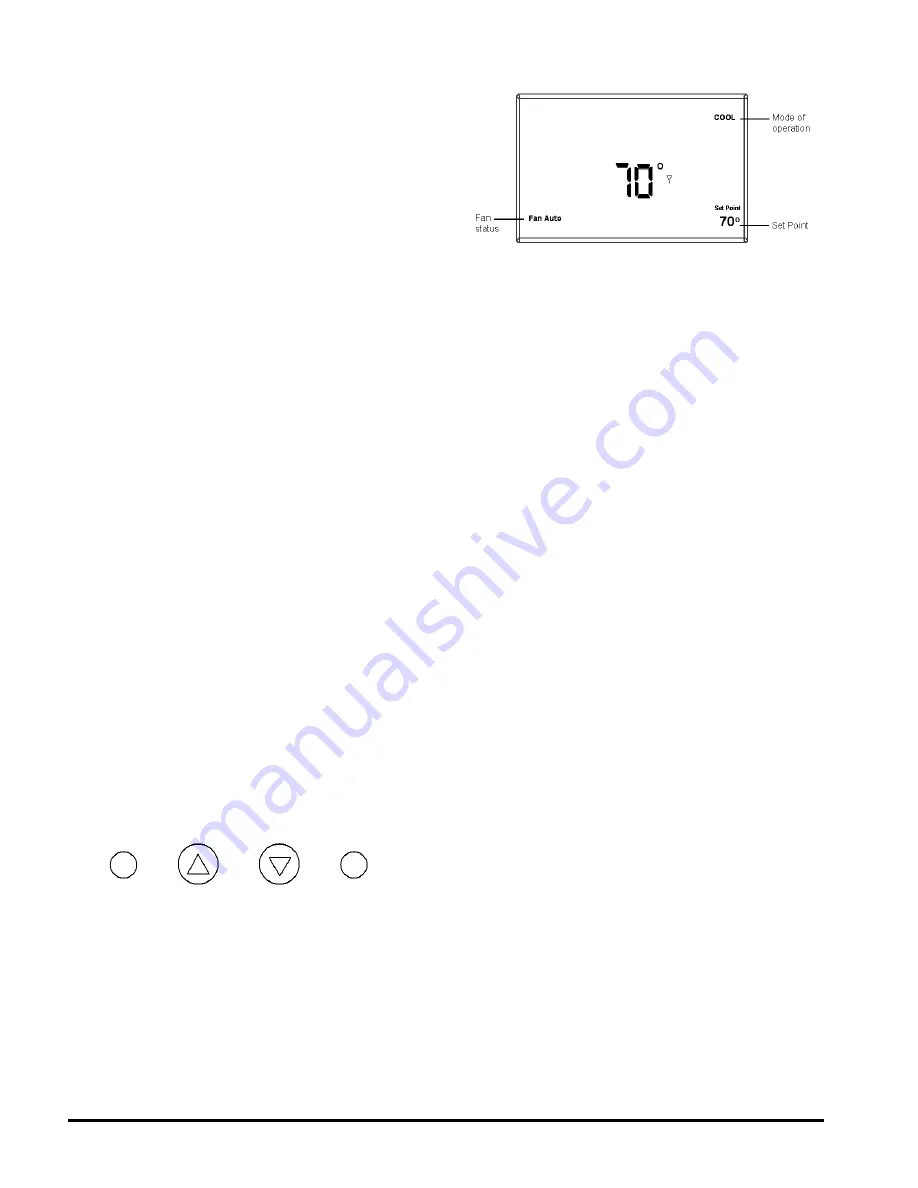
locations.  Figure  4  shows  the  display  items  that  are 

changed by these four buttons in normal operation.

Figure 5. General Operation Display

Note that the UP, DOWN and HEAT/COOL buttons 

are also used in setting the clock and programming the 

thermostat, and linking to nodes. This will be covered 

in the following sections of the manual.

Four buttons located on the left side of the thermostat 

(refer to Figure 1 & 11) control display of temperature in 

either Fahrenheit or Celsius, programming, clock setup 

and control of whether the thermostat is under manual 

or program control.

•   F / C – Toggles Fahrenheit Celsius display 

•   Program set up button

•   Run – Sets program or manual mode of    

 operation 

•  Clock set up button 

Backlight

A single button on the right hand side of the thermostat 

activates  the  display  backlight.  When  pressed,  the 

backlight will illuminate the display briefly and turn off. If 

other buttons are pressed immediately after the backlight 

button,  the  display  will  stay  illuminated  until  a  few 

seconds after all button activity has ended. Backlighting 

takes significant energy from the batteries and should be 

used sparingly. Frequent use of the backlight function 

will noticeably reduce battery life.

Setting The Clock

In all setup modes, the T9000 will flash the display 

item  you  are  about  to  change.  The  UP  and  DOWN 

buttons change settings, the HEAT/COOL button is used 

to move to the next item.  

To set the clock, you will use the buttons marked 

CLOCK, UP, DOWN, and HEAT/COOL.

Summary of Contents for OM 897

Page 1: ...mber 668111001 Date January 2008 Wireless Temperature Control For McQuay Applied Package Terminal Air Conditioners and Heat Pumps For replacement parts call 1 800 377 2787 2008 McQuay International www mcquay com 800 432 1342 OM 897 Applied PTAC Page 1 of 12 ...

Page 2: ... Light 4 Setting the Clock 4 5 Thermostat Programming 5 Navigating 6 Exiting the Program Mode 6 Run Button 6 Program Manual Operation 6 Changing Temperature 6 While Running a Program 6 Installing and Removing Nodes Installing Nodes 6 7 Installing Multiple Nodes 8 Uninstalling Nodes 9 Thermostat Reset 9 Frequently Asked Questions 10 11 ...

Page 3: ...lightonthethermostat display when the batteries are within approximately one week of being exhausted The T9000 is designed to use standard AA size 1 5 volt alkaline batteries If the batteries become completely depleted the heating cooling system will go to the Off state Replacing Batteries Toopenthethermostat usebothhandsandpressthe two push tabs on the bottom of the thermostat housing withyourthu...

Page 4: ...rature up or down and changing the operating mode of the thermostat See Figure1 11forfrontviewofthethermostatandbutton locations Figure 4 shows the display items that are changed by these four buttons in normal operation Figure 5 General Operation Display Note that the UP DOWN and HEAT COOLbuttons are also used in setting the clock and programming the thermostat and linking to nodes This will be c...

Page 5: ...isplayed in the upperrightsideoftheLCDscreen Figure1 forinstance shows a thermostat in COOL mode The mode the thermostat is in when the PROGRAM button is pressed is the mode that will be controlled by the program If it is in the cool mode as shown in Figure 1 the program entered will be stored as the program for cooling To program the thermostat you will use the PROGRAM HEAT COOL UP and DOWN butto...

Page 6: ...r65 scheduledtostartat11 00 PM If during the Evening time period you desired the space to be warmer you could press the UP button to raise the temperature set point The thermostat will hold that temperature until the next program period at which point the temperature will adjust to the programmed temperature set point for that period In this case the Night period is set for 11 00 PM and 65 Install...

Page 7: ...T COOL button to select the node number Step 4 Thecontrolnodecanbeinstalledtoathermostatasa HEAT only COOLonly or HEAT COOLnode After selectingthenodenumber theHEATand orCOOLicon will flash in the upper right hand quarter of the display is shown in Figure 8 Press the UPbutton to scroll through the following three choices Heat Install node as a heating only control Cool Install node as a cooling on...

Page 8: ...anged the Please Wait message is extinguished and a Good message will appear as shown in Figure 10 Figure 10 Install Link Display If another node is to be installed to this thermostat press the HEAT COOL button again The Install icon will flash As was done previously press the HEAT COOL button Step Two The node number will begin blinking select the node number by one using the UP button and contin...

Page 9: ...installednode s linking information is removed from the nodes and the thermostat pleasewait messagewillbe extinguished and a Good message will appear as shown in Figure 10 Thermostat Installation Reset In the event there is difficulty installing a node perform the following Step 1 Press the SW4 INSTALL button inside the thermostat The install icon will flash You only need to begin the installation...

Page 10: ...that one unit blows air directly on some people The thermostat in this case will not continuously look for a missing node if that one unit is powered off When my a c turns off I can t immediately make it run again This is normal What you are experiencing is called in anti short cycle delay Because of high pressure in the air conditioning compressor system it s not a good idea to start your air con...

Page 11: ...temperature will be displayed Refer to Figure 7 Next adjust the set point temperature to minimize system operation For example you could adjust to a set point of 85 F in cooling or 65 F in heating staying mindful of what your temperature selection could affect such as plants and animals that stay in your home while you are away During the cooling season consider humidity as well as roomtemperature...

Page 12: ...t us at www mcquay com and click on training or call 540 248 9646 and ask for the Training Department Warranty All McQuay equipment is sold pursuant to its standard terms and conditions of sale including Limited Product Warranty Consult your local McQuay Representative for warranty details Refer to Form 933 43285Y To find your local McQuay Representative go to www mcquay com This document contains...

Reviews: