background image


25 

Explanation of System Constant Setting by Symptom and Purpose 


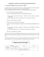
1.  The station lamp blinks in red at check (System constant P) 

 
Double feed detection cannot be performed at check.  Accordingly, the lamp blinks in red at check when the 
sensitivity of the paper feed photo sensor does not match the applied paper. 
The red lamp blinking condition is classified into 2 cases by paper quality and sensor sensitivity. 
 

1.  The sensor sensitivity is weak for paper thickness 

In this case, the station lamp blinks more slowly than blinking counter [Err]. 
 
(1) Clear the error and make a check again.  With this, the collator adjusts the sensitivity 

automatically. 

(2)  Set the system constant P value to a stronger value so that this value may be proper. 
 
The above 2 countermeasures are available. 


2.  The sensor sensitivity is stronger for paper thickness. 

In this case, the station lamp repeats 3-time blinking.  (This is slightly faster than blinking counter 
[Err].) 


(1) Clear the error and make a check again.  With this, the collator adjusts the sensitivity 

automatically. 

(2)  Set the system constant P value to a weaker value so that this value may be proper. 
 
The above 2 countermeasures are available. 

 
When the sensor sensitivity is too strong for paper thickness, the presence of paper may not be detected.  In 
this case, the only countermeasure to be taken is to manually set the system constant P value to a weak 
value. 
 
The system constant P adjusts the sensor sensitivity by operating the output of the luminous side of the 
paper feed photo sensor.  For the system constant P, 15 different values can be set as below. 


Indication 

Counter Contents 

of 

indication 

Operation Remarks 

1000 digit 


1 digit 

Current luminous intensity  Increment by 1 with the “4” key. 

Decrement by 1 with the “0” key. 


1 ,   2 .   3 ,   4 ,   5 ,   6 ,   7 ,   8 ,   9 ,   A ,   b ,   c ,   d ,   E ,   F

(Weak Strong) 

Summary of Contents for FC-10

Page 1: ... 0 SERVICE MANUAL for Tabletop Paper Collator FC 10 A PRODUCT OF CORPORATION The Leader in Paper Handling Equipment 1 800 223 2508 www mbmcorp com APRIL 25 2005 ...

Page 2: ... 1 1 ...

Page 3: ...mode 19 11 Changing the system constants 20 11 1 Facts about system constants 20 11 2 Adjustment of the paper feed photo luminescence intensity 22 11 3 Releasing double feed detecting function 23 11 4 Initializing the system constant return to factory set value 23 11 5 Supplementary explanation of system constants by purpose 24 11 6 System constant table when a post process machine is connected 32...

Page 4: ...frequently occurs 40 12 16 Empty feed frequently occurs 40 12 17 Empty feed or jam frequently occurs 41 12 18 Paper is fed aslant 41 12 19 DOUBLE FEED lamp lights though a single sheet is fed 42 12 20 Paper jam frequently occurs 42 12 21 Stacked paper is not neatly aligned 43 12 22 Ejected paper edge is curled 43 12 23 Ejected paper is stained 44 ...

Page 5: ...pressure shifting lever 5 Power switch 6 Circuit breaker 7 Paper feed roller 8 Left cover 9 Back door 10 Stacking pole 11 Stacking table 12 Inlet 13 Outlet to connect optional stapler puncher and stacker 14 Right connector Connect to right tower 15 Light connector Connect to left tower option 16 Right cover 17 Shift lever for paper direction 18 Auxiliary table 19 Paper detection wire ...

Page 6: ...tes an error in the left side collator when lighted red 5 COUNTER Displays the number of collated sheets Err is displayed in the event of an error 6 SHEET SET Press the key to change the number of collated sets and the number of batches in Insert and Programmed Insert modes 7 CHECK lamp Lights green to when trial feed is complete 8 PAPER JAM lamp Lights red should a paper jam occur 9 DOUBLE FEED l...

Page 7: ...ll occur Also used to input number 2 for the pre set counter 18 SPEED 3 key When lighted green high speed collation occurs when not lit collation will be slow Also used to input number 3 for the pre set counter 19 ALTERNATE 4 key When lighted green Alternate collation is selected when not lit Normal collation is selected Also used to input number 4 for the pre set counter 20 CRISSCROSS 5 key When ...

Page 8: ... air Loosen the force lightly and pinch them again after bending 3 Jog and align the sheets vertically 3 Align sheets at the edges and insert them until they lightly strike the forward guide Failure to properly align sheets may lead to double feed or no feed 4 Make sure any ink on the paper is dry Let ink dry before loading paper Wet ink soils the feed rollers and the separator rubbers It can lead...

Page 9: ... is used independently or a staple is connected with it load the paper in order from the bottom 10th station This way prevents disorder in paper ejection and facilitates the processing speed In case optional machines are connected with the collator such as two towers of the collator are connected with a large capacity stacker or a booklet maker load the paper in order from the top 1st station This...

Page 10: ...lay Other display Possible cause Corrective Action CHECK lamp and the relevant station lamp light green They light when checking is completed Use the machine as they are Station lamp lights red JAM lamp and the relevant station lamp light flashes red Paper remains in the paper feed photo sensor Remove the paper shielding the photo sensor EJECT lamp lights flashes red Paper remains in the paper sta...

Page 11: ... run out Load paper on station End EJECT lamp flashes red Stacking table is full Remove the paper in stacking table and continue collation Err0 Error has occurred at nonvolatile memory Stored values are deleted however the machine can be used as it is If it occurs frequently it will be necessary to replace the operation circuit board Err1 ERROR R or L flashes red Communication error occurs Make su...

Page 12: ...ugh 6 y Paper ejection photo sensor y Full stacking photo sensor y Table lifting y Crisscross starting point y Back door y Left side connector 25P y Right side connector 15P y Paper feed clutch Stations 1 through 10 y Lifting motor y Crisscross motor y Speed control circuit board y Paper switch y For writing in ROM y Encoder photo sensor y Transformer ...

Page 13: ...12 5 2 Speed control circuit board Operation circuit board Main motor Terminal block Speed control circuit board ...

Page 14: ...13 6 WIRING DIAGRAM ...

Page 15: ...14 7 CIRCUIT BOARD DIAGRAM 7 1 Operation board ...

Page 16: ...15 7 2 Speed control circuit board ...

Page 17: ...ator Caution When the paper feed rubber rollers are replaced mount them on the paper feed rollers holders so that the white dot of the rubber rollers is on the right hand side In addition after mounting the paper feed rollers on their holders roll them on a flat surface such as a desktop to make sure they are mounted horizontally If mounted askew problems like paper feed failure or double feed may...

Page 18: ...17 9 DIAGRAM FOR BELT INSTALLATION ...

Page 19: ... Checking the stapler puncher Cannot be used when stapler puncher is not connected S Test sequence mode Do not use this mode T Durability operation mode Do not use this mode 10 3 Checking the operation Key operation Function Display Remarks SPEED 3 Changeover between high and low speeds SPEED lamp lights lights out CRISSCROSS 5 Crisscross operation CRISSCROSS lamp PROGRAM 8 Main motor rotation The...

Page 20: ...ws while it is halfway MODE lamp Status of full stacking It lights when paper is fully stacked SPEED lamp Display of collation speed It lights when high speed collation is set CRISSCROSS lamp Status of crisscross starting point switch It lights when the switch is set at crisscross starting point 10 5 Photo sensor check mode While the photo sensor check mode is set the status of the paper feed phot...

Page 21: ...are changed 11 1 Facts about system constants 1 In order to move to system constants setting mode 1 Start based on the normal mode 2 Keep pressing 0 key for three seconds Then the counter displays P x x represents the current set value 3 y Press the MODE key to move to next item y Press the RESET key to move back to the previous item y Press the CHECK key to make a tentative setting The set value ...

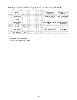
Page 22: ...ejected to right side d SOL ON Interval 1 d180 Interval until the clutch placed at lower level starts to move when paper is ejected to right side E SOL ON Interval 2 E230 Not used F Left side ejection SOL On time F448 Time in which paper feed roller is rotating for feeding paper when paper is ejected to left side G SOL ON Interval 1 G180 1 Interval until the clutch placed at lower level starts to ...

Page 23: ...e paper thickness it may occur that the light penetrates the paper resulting in empty feed error In this case luminescence intensity must be reduced manually The following procedures should be taken 1 Press 0 key for three seconds to set the system constants setting mode P x will be displayed 2 Lower the value of luminescence intensity on display Press the 4 key to increase the value by one Press ...

Page 24: ...n to the initial value when the power supply is cut off Press the START key to memorize the set value The altered value will be stored even if the power supply is cut off 11 4 Initializing the system constant return to factory set value In case the machine work becomes unstable after the system constants are altered for adjustment the system constant can be returned to the factory set values 1 Tur...

Page 25: ...using a large capacity stacker or Foldnak System constant n 26 5 Changing the paper feed interval between stations at connection with after processing machine System constant G 27 6 Adjusting the paper feed timing between the left and right towers at 2 tower connection System constant S 29 7 Ejecting paper to the left side without an external connector System constant J 30 8 Changing the error out...

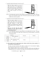
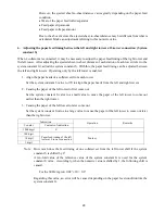
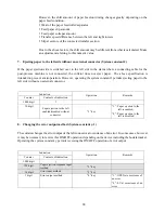
Page 26: ...y is stronger for paper thickness In this case the station lamp repeats 3 time blinking This is slightly faster than blinking counter Err 1 Clear the error and make a check again With this the collator adjusts the sensitivity automatically 2 Set the system constant P value to a weaker value so that this value may be proper The above 2 countermeasures are available When the sensor sensitivity is to...

Page 27: ...ses the time from the passage of paper through the paper feed photo sensor at the end till the execution of the next paper feed 1 at collator side can be adjusted in the range of 0 to 60 seconds by operating the system constant L 1 In case of paper ejection to the booklet maker in case of connection with KAS or Plockmatic booklet maker without control the electric signal is not communicated betwee...

Page 28: ...value to System constant L 1 0 or more The system constant n varies depending on the connected device Basic value n 5 0 When a stapler puncher or large capacity stacker is connected n 3 0 5 Changing the paper interval between stations at connection with after processing machine System constant G When the booklet maker is connected the interval of paper feed timing with the next station can be chan...

Page 29: ...ty stacker or a jogger use this setting However note that when the system constant G is set to 0 a paper feed cannot be normally performed 1 3 2 4 1 2 3 4 Note For the right paper ejection the same setting can be performed by the d value The paper stacked on the bottom station shelf comes out first but is ejected to the bottom of a collated set on crisscross stacker Indication Counter Contents of ...

Page 30: ... each tower Set the system constant S value to 170 to align the paper heads from the left and right towers 2 Causing the paper of the left tower to first come out Set the system constant S value to a small value to cause the paper of the left tower to come out earlier than the right tower 3 Causing the paper of the left tower to later come out Set the system constant S value to a large value to ca...

Page 31: ...soperation However operating the system constant J permits ejecting paper to the left side without an external connector Indication Counter Contents of indication Operation Remarks 1000 digit J 10 digit Paper ejection to the left enabled disabled without connector 3 key 1 Paper ejection to the left is enabled 0 Paper ejection to the left is disabled 8 Changing the error output method System consta...

Page 32: ...r input method 3 key 1 digit Error output method 4 key 1 Error at 5 V 0 Error at 0 V Note The error input of the collator is pulled up to 5 V Accordingly when no device is connected 5 V is input 10 Changing the paper ejection response method System constant y 3 When the after processing machine is connected there is the case that it may be necessary to reverse the paper ejection response input met...

Page 33: ...ion n 5 0 n 3 0 1 Shortening the paper ejection response wait time Elongating the paper ejection response wait time b Paper feed photo sensor luminous intensity All stations b1xx Working with thin paper Working with thick paper C Paper feed clutch ON time Right paper ejection C448 Shortening the paper feed clutch ON time Elongating the paper feed clutch ON time d Paper feed clutch ON Interval Righ...

Page 34: ...nsitivity at 0 Raising the paper feed sensitivity at 1 r Initial value of paper feed photo sensor check time r 420 Shortening the paper feed photo sensor check time at check Elongating the paper feed photo sensor check time at check SH Unused SH 30 SL Unused SL 20 J Left paper ejection without connector J 000 Disabling left paper ejection without connector at J000 Enabling left paper ejection with...

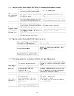
Page 35: ...een pins 5 and 6 cannot be detected The power transformer is faulty The situation remains the same after all connectors except one at the operation circuit board CN 10 are removed The operation circuit board is faulty Remove the cover on the operator side Check which connector is it to disable the machine from starting up when it is removed Replace the relevant harness assembly 12 2 Paper is not f...

Page 36: ...RT key is pressed Buzzer sounds pip pip when the START key is pressed CHECK lamp is not lit Continue checking Main motor does not rotate Refer to 12 2 Paper is not fed though the CHECK key is pressed Main motor does not rotate Refer to 12 3 Paper is not fed though the CHECK key is pressed Main motor rotates 12 5 Processing speed does not reduce while the low speed is selected The number of station...

Page 37: ... is out of order 12 7 Main motor does not rotate Remove the cover on the operator side and check the status while setting the TEST mode DC5V cannot be detected between pins 7 and 8 of the operation circuit board CN 12 when the RESET key is pressed to rotate the motor The operation circuit board is defective Remove the cover on the anti operator side and check the working status while setting the T...

Page 38: ...not be detected at the operation circuit board CN 13 when the START key is pressed The operation circuit board is faulty Paper feed clutch emits working sound when the START key is pressed The screws fixing the clutch and shaft are loosened DC24V cannot be detected at the connector of the paper feed clutch Check the paper feed clutch harness In case the clutch does not work at all stations it may ...

Page 39: ...e of crisscross motor is between 50 and 150 Ω The operation circuit board is faulty Remove the cover on the operator side and check the working status while setting the TEST mode Crisscross motor is out of order 12 10 EJECT lamp remains lit Stacking table is full Remove the paper It lights out if the stacking table is removed The stacking table is not properly set Check if the machine is installed...

Page 40: ... and check the status while the TEST mode is set I O circuit board is defective 12 12 DOOR lamp remains lit Check exterior conditions Back door is open Close the back door When door switch connector is removed voltage between terminals on the operation circuit board is DC4V or less Check the motor harness Remove the face cover on the operator side There is no continuity between COM and NO of the d...

Page 41: ...eparator rubber Paper feed pressure is strong Weaken the paper feed pressure Separator pressure is weak Strengthen the separator pressure 12 16 Empty feed frequently occurs Sheets are not neatly set on the paper feed table Arrange the sheets neatly Edge of paper is curled Correct the curl Turn the paper upside down Take that as the order of stacking also becomes reverse Paper not specified in the ...

Page 42: ...direction Reset the paper feed roller so that its white dot will be on its right side Separator rubber is stained Clean the separator rubber using alcoholic or detergent Separator rubber is worn Replace the separator rubber Paper feed roller is stained Clean the paper feed rubber using alcoholic or detergent Paper feed roller is worn Replace the paper feed roller 12 18 Paper is fed aslant Sheets a...

Page 43: ...ing function and release the double feed detecting function 12 20 Paper jam frequently occurs Guides and pole of the stacking table are not set to fit the paper size Set the guides etc 5 locations to fit the paper size Sheets are not neatly set on the paper feed table Align the paper and set the paper feed guide closely Edge of paper is curled Correct the curl Turn the paper over Take that as the ...

Page 44: ... is used Use paper specified in the specifications Checking of external conditions Paper has electrostatic charge Eliminate the electrostatic charge by wiping off the four corners of paper with tightly wrung cloth Remove the cover on the anti operator sdie and check the status Motor pulley for a different frequency is used Use the motor pulley fit for the frequency 013 gear teeth 12 22 Ejected pap...

Page 45: ...ined Clean the paper feed roller using alcoholic or detergent Separator rubber is stained Clean the separator rubber using alcoholic or detergent Dual feed roller and flat belt are stained Clean the dual feed roller and flat belt using alcoholic or detergent Paper stacking roller is stained Clean the paper stacking roller using alcoholic or detergent ...

Reviews: