8
1030658 Rev.A 09/05
SY
STEM LA
Y
OUT
Page 1: ...v hicule est dot d un d marreur distance Pour r duire les risques de blessures graves ou mortelles mettre le d marreur distance en mode service et d brancher la batterie du v hicule avant d effectuer...
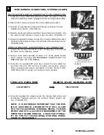
Page 2: ...hillips screw behind each panel FIGURE E f Remove the automatic shifter knob by carefully unscrew ing the shifter knob FIGURE F g Using a fiber stick remove the automatic shifter bezel on the center c...
Page 3: ...Slide the removed white clip into position on the A pillar panel FIGURE L 2 Clean mounting spot with an alcohol pad prior to mounting Mount the dipole antenna to the windshield 210mm to the right of...
Page 4: ...ie wraps FIGURE O Q 3 Route the hood safety switch wiring along the cowl panel tucking under the cowl panel where possible into the engine compartment towards the hood release cable grommet FIGURE O R...
Page 5: ...h wire to harness as shown FIGURE W d Pull fish wire and wiring through hood release cable opening FIGURE O page 4 e Tape the hood safety switch wires against the fish wire and electrical tape in plac...
Page 6: ...SYSTEM 4 FIGURE Z 5 15 15 15 15 15 15 5 15 15 15 15 15 15 15 HVAC 1 HVAC 2 MAIN B IGNITION DOME LIGHT PK LIGHTS DOOR LOCKS 15 TRUNK RELEASE To Immobilizer Interface Module FIGURE BB FIGUREAA REMOTE EN...
Page 7: ...CH MOUNTING WIRE CONNECTIONS 1 Locate the BLACK ORANGE and GRAY RED wire from the remote start system harness 2 Locate the wires listed below If the hood safety switch wire has a ground ringlet termin...
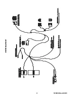
Page 8: ...8 1030658 Rev A 09 05 SYSTEM LAYOUT...
Page 9: ...cing the ignition key opening FIGURE HH II 5 Using a supplied tie wrap secure the antenna coil FIGURE HH II FIGUREGG FIGUREHH FIGUREII WIRE HARNESS CONNECTIONS STEERING COLUMN 9 IGNITION SWITCH CONNEC...
Page 10: ...steering wheell 2 Using a razor knife carefully cut back 1 2 of the plastic shield ing to expose the wiring BE EXTREMELY CAREFUL NOT TO DAMAGE ANY OF THE WIRES 3 Using the 1 supplied IDC wire tap con...
Page 11: ...of the IDC wire tap and crimp in place with pliers 10 REMOTE START HARNESS VEHICLE WIRE GREEN YELLOW GREEN YELLOW FIGUREQQ EMERGENCY OVERRIDE PROGRAMMING BUTTON MOUNTING 1 Locate the previously remov...
Page 12: ...rd panel and re secure the weather seal c Secure the center console panel and re install the 3 phillips screws around the shifter assembly and 1 phillips screw on each side of the lower center console...
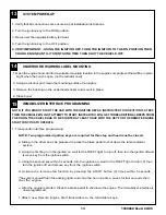
Page 13: ...he brake pedal to shut down the remote starter system b Using the first key turn the ignition on wait for the THEFT light to turn off then turn the ignition off and remove key from the ignition switch...
Page 14: ...ake pedal The vehicle should shut off 4 KEY IN SENSE Insert the ignition key into the ignition switch but keep in off position activate the remote engine start function the vehicle should flash the li...
Page 15: ...will need to be adjusted to shutdown the vehicle when the hood is raised to the full upright position 1 Raise and prop the vehicle s hood 2 The hood switch cylinder should be bend away from the hood...
Page 16: ...DOOR UNLOCK OUTPUT PROGRAMMING OVERIDE BUTTON PROGRAMMING OVERIDE BUTTON DRVR S UNLOCK OUTPUT TRUNK OUT DRVR S UNLOCK OUTPUT TRUNK OUT PROGRAMMING OVERIDE BUTTON PROGRAMMING OVERIDE BUTTON HOOD OPEN S...
Page 17: ...E ATTENTION Installation Instruction change for P N 0000 8F L05B The Fuse placement position changed for REMOTE START SYSTEMS on all Mazda 5 vehicles The Dome Light Fuse must be placed in the positive...
Page 18: ...e side of Ignition Coil in pin 2BE 2006 2007 models or pin 2G 2008 models of the 60 pin front connector at the PCM Refer to FIGURE A B for proper connector and pin location 4 Using a razor knife caref...
Page 19: ...ing option 2 g Press and release the brake pedal The horn will beep 3 times indicating option 3 h Press the START button on the transmitter one time i Press and release the programming button a third...
Page 20: ...ns b Ensure brake pedal is not depressed c Ensure good connection and correct vehicle brake wire See Step 10 of Installation Instructions d Disengage Service Valet Mode See Page 4 of Owner s Manual 5...