


24
Date:
VIN:
Approved
Checked
Person in
charge
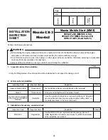
INSTALLATION
INSPECTION
SHEET
Mazda CX-3
Mazda2
Mazda Mobile Start (MMS)
0000-8F-Z80 (MMS ECU Kit)
0000-8F-P07 (MMS Harness Kit)
KD53-V7-629 (Hood Switch)
Perform the following inspections.
WARNING
•
Before starting the engine, make sure there are no persons in front of or behind the vehicle, or around the engine
compartment. Otherwise a serious accident could result by the vehicle suddenly moving.
•
Do not start the engine in a place like a garage or other placer with poor ventilation. Otherwise, poisoning or asphyxation
could result from accumulation of exhaust gas.
•
Always set the wheel blocks on level ground before performing the verification.
1. Inspection items after installation
•
Verify the fitting between the vehicle part and the installed part, and inspect for damage or dirt.
Check
2. Vehicle parts reinstallation
Inspection Parts
Inspection Items
Inspection
Check
Negative battery cable
Torque check
Are the battery cables securely tightened to the terminals?
Ground
Torque check
Is the ground bolt tightened to the proper torque?
Function restore procedure
after removal / Installation
of battery
Operation
Have the vehicle's functions been restored by referring to "Required
servicing after disconnecting connecting negative battery cable", in
the workshop manual or the owner's manual?
3. Installation of accessory, operation check
Inspection Parts
Inspection Items
Inspection
Check
MMS ECU
Registration
Has the MMS ECU been registered and checked per Section 9
(MMS Registration Procedure) and Section 10 (MMS Check Mode)
of the installation instructions?.


