background image

9

1031012 Rev.A 09/05

IMMOBILIZER INTERFACE RIBBON CABLE MOUNTING

9

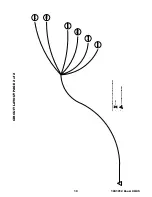
1. Route the immobilizer interface (previously installed) ribbon cable

to the ignition switch, making sure to keep it away from any moving
parts.

2. Following the instructions on the supplied ampule of adhesive primer,

apply a thin coating to the entire transceiver antenna ring (black plastic
ring around key switch, FIGURE II) and to the ribbon cable.

3. Remove the backing from one side of the supplied 2-way tape and apply

tape around the transceiver antenna ring (black plastic ring around key
switch, FIGURE JJ) keeping the tape off of the rounded part of the igni-
tion switch face and trimming excess 2-way tape if necessary.

4. Remove the remaining backing on the 2-way tape and position the ribbon

cable around the transceiver antenna ring, with the striped side facing
the ignition key opening. (FIGURE KK)

5. Using a supplied tie wrap, secure the antenna coil. (FIGURE KK)

FIGURE KK

FIGURE II

FIGURE JJ

Summary of Contents for 0000-8F-L10

Page 1: ...ing any service on the vehicle Ce v hicule est dot d un d marreur distance Pour r duire les risques de blessures graves ou mortelles mettre le d marreur distance en mode service et d brancher la batte...

Page 2: ...roud and remove the shroud FIGURE D and E g Remove the lower center console kick panels from both driver and passenger sides by using a fiber stick to pull the plastic center button of the plastic fas...

Page 3: ...the weather seal along the A pillar 2 FIGURE J FIGURE K HOOD SAFETY SWITCH MOUNTING 1 Using 2 supplied 1 4 self drilling screws and 2 supplied lock washers secure the hood safety switch to the drivers...

Page 4: ...wire to harness as shown FIGURE T d Pull fish wire and wiring through hood release cable opening FIGURE L page 3 e Tape the hood safety switch wires against the fish wire and electrical tape in place...

Page 5: ...DOME LIGHT PK LIGHTS DOOR LOCKS 15 TRUNK RELEASE To Immobilizer Interface Module FIGURE Y FIGURE X REMOTE ENGINE START MODULE AND IMMOBILIZER INTERFACE MOUNTING 5 Tie Wraps REMOTE ENGINE START MODULE...

Page 6: ...SAFETY SWITCH MOUNTING WIRE CONNECTIONS 1 Locate the BLACK ORANGE and GRAY RED wire from the remote start system harness 2 Locate the wires listed below If the hood safety switch wire has a ground ri...

Page 7: ...ONNECTION LOCATED AT PIN N OF THE J 04 CONNECTOR TOP OF PJB BLACK REC TRUNK AJAR INPUT CONNECTION LOCATED AT PIN X 5 DR PIN Z 4 DR J 06 CONNECTOR BOTTOM OF PJB BLACK WHITE DOOR UNLOCK OUTPUT LOCATED A...

Page 8: ...tart harness 8 way male connector into the factory ignition harness and replace the GREY secondary latch FIGURE EE MULTIFUNCTION SWITCH CONNECTOR 1 Locate the 12 way WHITE multifunction switch connect...

Page 9: ...FIGURE II and to the ribbon cable 3 Remove the backing from one side of the supplied 2 way tape and apply tape around the transceiver antenna ring black plastic ring around key switch FIGURE JJ keepin...

Page 10: ...e with pliers 10 WIRE HARNESS CONNECTIONS PASSENGER UNDERDASH 1 Route the passenger kick panel harness with six 6 loose wires across the driver s side lower dash using 1 supplied tie wrap secure the h...

Page 11: ...CLE WIRE BLUE DOMELIGHTINPUT OUTPUT BLACK BLUE Pin U FIGURE QQ REMOTE START HARNESS VEHICLE WIRE BLACK HORNOUTPUT BLACK Pin N FIGURE OO RE MOUNT PJB 1 After all connections have been made re mount the...

Page 12: ...the dashboard panel and re mount the rubber weather seal EMERGENCY OVERRIDE PROGRAMMING BUTTON MOUNTING 1 Locate the previously removed driver s side kick panel cover 2 Drill a 9 32 hole at the top o...

Page 13: ...place d Re install 1 phillips screw on the lower left side of the driver s side dashboard panel FIGURE WW and re se cure the hood release handle 14 FIGUREUU FIGURE VV FIGURETT FIGUREWW SYSTEM POWER U...

Page 14: ...seconds The system should flash the parking lights and chirp the horn one time pause for four seconds then start the engine e After the engine is started Press the brake pedal to shutdown the engine T...

Page 15: ...ystem by pressing the unlock button on the transmitter and try starting the vehicle again the vehicle should crank and start at this time shut the vehicle off Remote Engine Start Functions 1 REMOTE EN...

Page 16: ...amming button The horn will beep 4 times indicating the system has entered the option bank c Press the PANIC button to enter the option number The horn will beep the number of times equal to the optio...

Page 17: ...response is obtained Horn should beep one time and parking lights should flash one time once shock pressure level is obtained Full trigger testing Increase pressure of slap until response is obtained...

Page 18: ...EXT SENSOR INPUT MEMORY 2 OUTPUT AUX 4 TRUNK AJAR INPUT TRUNK REL DR S DR UNLK SW INPUT MEMORY 1 OUTPUT AUX 3 REAR DEFROST OUTPUT AUX 2 NOT USED NOT USED NOT USED NOT USED CIRCUIT DESCRIPTION DOOR LO...

Page 19: ...Rev A 09 05 CIRCUIT LAYOUT PAGE 2 of 2 A A CONTINUED ON NEXT DRAWING 1 SPLICE 2 NOTE SPLICES MAY NOT BE LOCATED WHERE SHOWN 22BK GN C103 15 C103 7 22BK C99 30B 22BK WT C100 39B 22BL C99 29 22BK BL 22B...

Reviews: