


18
1031012 Rev.A 09/05
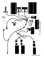
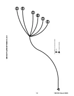
CIR
CUIT LA
Y
OUT P
A
GE 1 of
2
1
2
3
4
5
6
7
8
9
10
10-WAY PCT CAR START CONNECTOR
ACC
12
EXTENDED FUNCTION HARNESS
MAIN HARNESS
NOT USED
NOT USED
NOT USED
NOT USED
NOT USED
NOT USED
NOT USED
NOT USED
C103-15
NOT USED
NOT USED
NOT USED
C99-12
--
--
--
--
--
22
--
--
--
--
--
--
22
NOT USED
NOT USED
NOT USED
8
9
4
5
7
6
1
2
3
15
16
--
--
--
13
14
10
11
12
--
--
--
--
--
BK/GN
--
--
--
--
--
--
BK/RD
--
--
--
-
-
-
--
--
20
20
20
22
22
22
VIEW FROM TERMINAL END
9
11
12
10
6
7
8
3
4
5
21
23
24
22
20
19
15
16
17
18
VIEW FROM TERMINAL END
LD2
C99-30A
1
2
P2
LD1
HD1
C100-39A
C103-7
-
-
C99-30, C99-30A
P1
13
14
22
22
22
BK
BK/WT
BR
GY/RD
BL
BK
RD
--
--
BK/WT
BR
-
C100-39, C100-39A, C100-39B
ST-2
-
-
-
-
1E, 1E-A, 1E-B
B1
ST-1
IG1
459A
C99-29
22
14
-
-
-
12
16
14
12
22
22
BL
GY
-
-
-
-
GN/YL
RD
BK/OR
GY/BK
WT
BK/BL
VIEW FROM TERMINAL END
1
6
7
12
A
459A,459A-A,459A-B
WT
459D
459B
459F
459H
459J
459L
459A-B
GY
GN
22
22
BK/RD
PK
BK/YL
WT
22
22
22
22
22
459K
459C
459E
459G
459I
BK/GN
BK/OR
OR
BK/BL
YL
22
22
22
22
22
B1,B1-A,B1-B
KIS,KIS-A,KIS-B
B2,B2-A,B2-B,B2-C
IG1,IG1-A,IG1-B,IG1-C
IG2,IG2-A,IG2-B
WT
459D
459B
459F
459H
459J
459L
459A-A
GY
GN
22
22
BK/RD
PK
BK/YL
WT
22
22
22
22
22
459K
459C
459E
459G
459I
BK/GN
BK/OR
OR
BK/BL
YL
22
22
22
22
22
6
1
12
7
ACC,ACC-A,ACC-B
A
1
20BR
P2
P1
20BR
1
1
20GY/RD
HD1
22RD
LD1
22BK
LD2
20BK/OR
1E-A
20RD/WT
BRK
16BK/OR
1E-B
1
1
= CONTINUED ON NEXT DRAWING
1. = SPLICE
2.
NOTE: SPLICES MAY NOT BE LOCATED WHERE SHOWN.
TACH SENSE INPUT
BRAKE INPUT
ACTIVE OUTPUT
KEY-IN-SENSE INPUT
HVAC 1 OUTPUT IGNITION 2 OUTPUT
HVAC 2 FEED CIRCUIT DESCRIPTION
CAV
CIRCUIT NAME
B2
8
9
10
4
6 5
7
2
3
HVAC 2 OUTPUT
NOT USED
HVAC 1 FEED
COLOR
GA
RD/BK
20
-
-
-
GN/YL
12
YL
RD/WT -
-
PK/YL
BK/RD
BK/RD
12 12 16
B2-A
IG2
IG1-C
-
BRK
KIS
-
-
-
20
CIRCUIT NAME
CIRCUIT NAME
4
14
16 15
9
10
12
13
11
6
7
5
8
2
3
CAV
13
23
24
18
20 19
22 21
16
14
15
17
8
9
12
10
11
4
5
6
7
3 2
CAV
GA
FACTORY ALARM DISARM OUTPUT
TRUNK RELEASE DISARM INPUT
HEADLIGHT OUTPUT/AUX 1
EXT SENSOR INPUT
MEMORY 2 OUTPUT/AUX 4
TRUNK AJAR INPUT
TRUNK REL/DR'S DR UNLK SW INPUT
MEMORY 1 OUTPUT/AUX 3 REAR DEFROST OUTPUT/AUX 2
NOT USED
NOT USED
NOT USED NOT USED
CIRCUIT DESCRIPTION
DOOR LOCK SWITCH INPUT
FACTORY ALARM ARM OUTPUT
DOOR UNLOCK SWITCH INPUT
COLOR
TRNK REL/DRV DR UNLK REL OUTPUT
N/A - SIREN OUTPUT
DOOR UNLOCK OUTPUT
PROGRAMMING/OVERIDE BUTTON
DRVR'S UNLOCK OUTPUT/TRUNK OUT
PROGRAMMING/OVERIDE BUTTON
HOOD OPEN SWITCH INPUT
HORN RELAY OUTPUT DOOR AJAR SWITCH INPUT
LED LED
N/A - SIREN FEED
GA
DISARM INPUT
UNLOCK SWITCH SENSE INPUT
IGNITION 1 INPUT/OUTPUT
DOOR TRIGGER PULL-UP
STARTER INTERRUPT (MOTOR SIDE)
DOME LIGHT OUTPUT
PARKING LIGHT OUTPUT CIRCUIT DESCRIPTION
STARTER INTERRUPT (KEY SIDE)
DOOR LOCK OUTPUT
ARM INPUT
BATTERY
GROUND
COLOR
PARKING LIGHT (-) OUTPUT
6
EXT-2
HEADLIGHT (-) INPUT EXT-3
LEFT TURN SIGNAL (-) INPUT
EXT-1
FRONT FOG LAMP (-) INPUT
11
12
7
9 8
10
AUTOLAMP (-) INPUT GROUND
HIGH BEAM (-) INPUT
REAR FOG LAMP (-) INPUT
RIGHT TURN SIGNAL (-) INPUT
CIRCUIT DESCRIPTION
CIR NAME
2
4 3
5
CAV
COLOR
GA
PARKING LIGHT (-) OUTPUT
6
EXT-2
HEADLIGHT (-) INPUT EXT-3
LEFT TURN SIGNAL (-) INPUT
EXT-1
FRONT FOG LAMP (-) INPUT
11
12
7
9 8
10
AUTOLAMP (-) INPUT GROUND
HIGH BEAM (-) INPUT
REAR FOG LAMP (-) INPUT
RIGHT TURN SIGNAL (-) INPUT
CIRCUIT DESCRIPTION
CIR NAME
2
4 3
5
CAV
COLOR
GA
KIS-A
ST-1
CIR NAME
C456 IGNITION SWITCH CONNECTOR (SWITCH SIDE)
TERMINAL END VIEW
5
1
4
8
3
4
8
5
6
4
5
1
CAV NUM
1
2
TERMINAL END VIEW
20
12
12 12
IG2-A
B2-B
GA
20
12
B1-A
IG1-A
COLOR
STARTER
12V+ BATTERY
KIS +12V FEED
KEY IN SENSE
PRIME IGNITION
FUNCTION
12V+ BATTERY
RD
RD
RD/BK
GN/YL
BK/RD
YL
TOP VIEW
1
2
SIDE VIEW
ACC-A
7
8
14
12
BKIS
2ND IGNITION
ACCESSORY
PK/YL
GY/BK
KIS-B
ST-2
CIR NAME
C456 IGNITION SWITCH CONNECTOR (MOTOR SIDE)
3
5
6
4
CAV NUM
1
2
20
12
12 12
IG2-B
B2-C
GA
20
12
B1-B
IG1-B
COLOR
STARTER
12V+ BATTERY
KIS +12V FEED
KEY IN SENSE
PRIME IGNITION
FUNCTION
12V+ BATTERY
RD
RD
RD/BK
GN/YL
BK/RD
YL
ACC-B
7
8
14
12
BKIS
2ND IGNITION
ACCESSORY
PK/YL
GY
C-459 MULTI-SWITCH MALE CONNECTOR - 12 PIN
C-459 MULTI-SWITCH FEMALE CONNECTOR - 12 PIN
TERMINAL END VIEW
TERMINAL END VIEW


