Maytag Amana APCH32441 Installation Instructions Manual Download Page 11

11

NOTE: The PCBDM133 defrost controls are shipped 

from the factory with the compressor delay option 

selected. This will de-energize the compressor 

contactor for 30 seconds on defrost initiation and 

defrost termination. If the jumper is set to Normal, 

the compressor will continue to run during defrost 

initiation and defrost termination. The control will 

also ignore the low-pressure switch connected to 

R-PS1 and PS2 for 5 minutes upon defrost initiation 

and 5 minutes after defrost termination.

To check the defrost control for proper sequencing, 

proceed as follows: With power ON; unit not running.

1.  Jumper defrost thermostat by placing a jumper wire 

across the terminals “DFT” and “R”/” R-DFT” at 

defrost control board.

2.  Remove jumper from timer pins and jump across test 

pins on defrost control board. 

NOTE

: Do not use screwdriver or field supplied 

jumper to test the control.

3.  Set thermostat to call for heating. System should go 

into defrost within 21 seconds. 

4.  Immediately remove jumper from test pins.

5.  Using VOM check for voltage across terminals “C & 

O”. Meter should read 24 volts.

6.  Using VOM check for voltage across fan terminals 

DF1 and DF2 on the board. Should read line voltage 

(208-230 VAC) indicating the relay is open in the 

defrost mode.

7.  Using VOM check for voltage across “W”/”W2” & “C” 

terminals on the board. Should read 24 volts.

8.  If not as above, replace control board.

9. 

Set thermostat to off position and disconnect power. 

Remove jumper from defrost thermostat and replace 

timer jumper to the desired defrost time.

NOTE: Remove jumper across defrost thermostat 

before returning system to service.

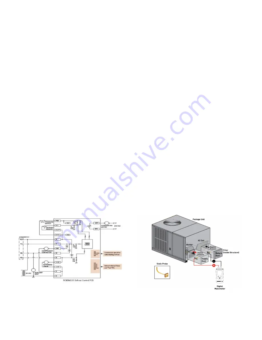
PCBDM133 Defrost Control

Figure 8

Testing Defrost Thermostat 

1.  Install a thermocouple type temperature test lead on 

the tube adjacent to the defrost control. Insulate the 

lead point of contact. 

2.  Check the temperature at which the control closes its 

contacts by lowering the temperature of the control. It 

should close at approximately 30°F. 

3.  Check the temperature at which the control opens its 

contacts by raising the temperature of the control. It 

should open at approximately 60°F. 

4.  If not as above, replace control. 

AIR FLOW MEASUREMENT AND 

ADJUSTMENT

After reviewing section on DUCTING, proceed with airflow 

measurements and adjustments. Unit’s blower curves 

(in Specification Sheets) are based on external static 

pressure (ESP, in. of W.C.). The duct openings on the unit 

are considered internal static pressure, so as long as ESP 

is maintained, the unit will deliver the proper air up to the 

maximum static pressure listed for the CFM required by the 

application (i.e. home, building, etc.).

In general 400 CFM per ton of cooling capacity is a rule 

of thumb. Some applications depending on the sensible 

and latent capacity requirements may need only 350 

CFM or up to 425 CFM per ton. Check condition space 

load requirements (from load calculations) and equipment 

expanded ratings data to match CFM and capacity.

After unit is set and ducted, verify ESP with a 1” inclined 

manometer with pitot tubes or a Magnahelic gauge 

and confirm CFM to blower curves in the specification 

sheets.  All units have multiple speed blower motors. If 

factory selected speed is not utilized, the speed tap can 

be changed. Never run CFM below 350 CFM per ton, 

evaporator freezing or poor unit performance is possible.

Total External Static Pressure

1.  Using a digital manometer measure the static 

pressure of the return duct at the inlet of the unit 

(Negative Pressure).

Mode

.



Total External Static

Figure 9

2.  Measure the static pressure of the supply duct 

(Positive Pressure).

3.  Add the two readings together.

Summary of Contents for Amana APCH32441

Page 1: ...or repair the equipment specified in this manual without proper training may result in product damage property damage personal injury or death WARNING RECOGNIZE THIS SYMBOL AS A SAFETY PRECAUTION All...

Page 2: ...y look the location over both the inside and outside of home Note any potential obstacles or problems that might be encountered as noted in this manual Choose a more suitable location if necessary IMP...

Page 3: ...inal tons of cooling Optional field installed heat kits are available in 5 8 10 15 and 20 KW The units can be easily installed in manufactured or modular homes with existing high static duct work The...

Page 4: ...letely unobstructed If units are to be located under an overhang there should be a minimum of 48 clearance and provisions made to deflect the warm discharge air out from the overhang Location Consider...

Page 5: ...ver the unit to prevent damage to the cabinet by the lift cables Spreader bars must be of sufficient length so that cables do not come in contact with the unit during transport Remove wood struts moun...

Page 6: ...lenum Application A suitable plenum or square duct must be constructed The duct cross sectional area should be determined by industry duct sizing manuals or air duct calculators On ductwork exposed to...

Page 7: ...NFPA NO 70 1984 or latest edition by using ground lug in the control box DO NOT EXCEED THE MAXIMUM OVERCURRENT DEVICE SIZE SHOWN ON UNIT DATA PLATE Fuses or HACR type circuit breakers may be used wher...

Page 8: ...er when servicing the unit WARNING HIGH VOLTAGE Disconnect all power before servicing or in stalling this unit Multiple power sources may be present Failure to do so may cause proper ty damage persona...

Page 9: ...upplemental heat Normally a Defrost cycle will take only 2 3 minutes unless system is low on charge or outdoor conditions are severe windy and cold The defrost control also provides for a 3 minute off...

Page 10: ...e heating requirement should there be a component failure of the heat pump such as a compressor or refrigerant leak etc Since the temperature of the liquid refrigerant in the outdoor coil on the heati...

Page 11: ...ple type temperature test lead on the tube adjacent to the defrost control Insulate the lead point of contact 2 Check the temperature at which the control closes its contacts by lowering the temperatu...

Page 12: ...or with a electronic control board ECM Motor The ECM motor provides many features not available on the traditional PSC motor These features include Improved Efficiency Constant CFM Soft Start and Stop...

Page 13: ...ltage power wire typically the black lead to the thermostat R Red wire in control box 5 Secure the dehumidistat ground wire typically the green lead to the ground screw to the unit s sheet metal contr...

Page 14: ...running on low stage with TXV application should have a subcooling and superheat within the range listed on the chart a If subcooling and superheat are low adjust TXV superheat then check subcooling N...

Page 15: ...to easily install the HKR HKP Series Electric Heat Kit Full Installation Instructions are included in this kit Please use this document for guidance in field equipping the package unit with electric h...

Page 16: ...Do not allow air entering the indoor coil to drop below 65 F Air below this temperature will cause low discharge pressure thus low suction pressure and excessive defrost cycling resulting in low heati...

Page 17: ...88 1022 989 Watts 179 190 203 210 225 243 249 268 CFM 1758 1715 1674 1637 1596 1557 1518 1474 Watts 394 406 418 430 443 455 466 474 CFM 2002 1935 1885 1827 1767 1732 1669 1618 Watts 498 521 516 534 55...

Page 18: ...gs for Single Two Stage Thermostat Speed Tap Switch 5 Switch 6 A OFF OFF B ON OFF C OFF ON D ON ON Cooling HP DIP Switch Settings CFM Switch 7 Switch 8 Plus 10 ON OFF Normal OFF OFF Minus 10 OFF ON Sp...

Page 19: ...81 294 305 318 330 CFM 1736 1679 1638 1598 1558 1520 1484 1441 Watts 356 372 382 395 408 422 433 442 CFM 1337 1297 1218 1155 1118 1088 1022 989 Watts 179 190 203 210 225 243 249 268 CFM 1758 1715 1674...

Page 20: ...t be within 10 of nameplate volts when unit is operating d Capacitor weak open or shorted d Check capacitor If defective replace Low suction cool compressor a a Iced evaporator coil a Defective overlo...

Page 21: ...A B PCH32441 66 34 27 30 Small PCH33041 66 34 27 30 Small PCH33641 66 34 27 30 Small PCH34241 66 34 32 35 Medium PCH34841 66 34 32 35 Medium PCH36041 66 34 32 35 Medium Model Duct Openings Supply Ret...

Page 22: ...A B PHH32441 66 34 27 30 Small PHH33041 66 34 27 30 Small PHH33641 66 34 32 35 Medium PHH34241 66 34 32 35 Medium PHH34841 66 34 32 35 Medium PHH36041 66 34 36 38 Large Model Duct Openings Supply Ret...

Page 23: ...minum Indoor Coil Cleaning Qualified Servicer Only This unit is equipped with an aluminum tube evaporator coil The safest way to clean the evaporator coil is to simply flush the coil with water This c...

Page 24: ...Type NG Natural Gas LP Liquid Propane Residential Package Outdoor Section ELECTRICAL Supply Voltage Measure L1 and L2 Voltage L1 L2 Compressor Amps Condenser Fan Amps PRESSURES TEMPERATURES Suction Ci...

Page 25: ...25 THIS PAGE IS LEFT INTENTIONALLY BLANK...

Page 26: ...26 THIS PAGE IS LEFT INTENTIONALLY BLANK...

Page 27: ...27 THIS PAGE IS LEFT INTENTIONALLY BLANK...

Page 28: ...o the feedback page GOODMAN BRAND AMANA BRAND GOODMAN BRAND AMANA BRAND PRODUCT REGISTRATION Thank you for your recent purchase Though not required to get the protection of the standard warranty regis...

Reviews: