Installation and Operational Instructions for
EAS
®
-Compact
®
overload clutch Type 49_._ _4._
Sizes 01 to 3
(B.4.14.1.EN)
13/11/2017 GC/NU/GH/SU
Chr. Mayr GmbH + Co. KG
Eichenstraße 1, D-87665 Mauerstetten, Germany
Tel.: +49 8341 804-0, Fax: +49 8341 804-421
Page 11 of 19
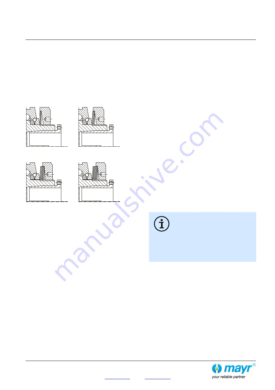
Cup Spring Layering (Fig. 6)
Correct cup spring layering is a prerequisite for problem-free
clutch function and torque adjustment.
For the lower torque range,
one
cup spring
(Type 49_.
5
_ 4._),
for the medium torque range,
two
cup springs (Type 49_.
6
_ 4._),
for the high torque range,
four
cup springs
(Type 49_.
7
_ 4._)
and for the maximum torque range
five
cup springs (Type 49_.
8
_ 4._) are installed.
1x layered
2x layered
Type 49_.
5
_4._
Type 49_.
6
_4._
4x layered
5x layered
Type 49_.
7
_4._
Type 49_.
8
_4._
Fig. 6
Mounting onto the Shaft
EAS
®
-Compact
®
clutches include cone bushings, shrink disks,
clamping hubs or keyways as part of the standard delivery.
During installation of cone bushings, shrink disks or
clamping hubs, please observe the following:
Recommended shaft tolerance for cone bushings: h6
Recommended shaft tolerance for clamping hubs: h6
Recommended shaft tolerance for shrink disk hubs: g6
Shaft surface: finely turned or ground
(Ra = 0.8 µm).
Shaft material: yield point at least 400 N/mm
2
,
e.g. C45 +QT, 42QT.
Degrease or remove conserving layers on the shafts and
bores before installing the clutch.
Greasy or oily bores or shafts do not transmit the
torques defined in the catalogue.
Mount the clutch or clutch hubs onto both shaft ends using a
suitable device and bring it / them into the correct position.
Tighten the tensioning screws (13) of the cone bushing (15)
in 2 steps cross-wise and then in 3 to max. 6 tightening
sequences evenly using a torque wrench to the torque stated
in Table 5.
Type 494.-:
Tighten the tensioning screws (22) in the shrink disks (20.1)
stepwise (in 3 to max. 6 tightening sequences) and cross-
wise evenly using a torque wrench to the torque stated in
Table 5.
Type 496.-:
Tighten the tensioning screws (34.2) in the shrink disks
(34.1) using a torque wrench evenly and one after the other
in max. 6 sequences to the torque stated in Table 5.
The transmittable torques of the shaft-hub connection are
dependent on the bore diameter and the quality of the drive
shafts used. Please observe the respective transmission
tables in the valid and applicable product catalogue.
The clutch or clutch hub carries out an axial
movement in the direction of the cone bushing
(15) when tightening the cone bushing (15).
Because of this effect, please ensure that on the
EAS
®
-Compact
®
clutch with steel bellows (Type
493._ _ 4.0), first one cone bushing is completely tightened
(e.g. Item 15), then the other (steel bellows) side (Item 24,
page 3).
Please also ensure during installation of Type 493._ _4.0 that
no axial pressure is placed on the steel bellows (can cause
damage).
De-installation
of the Cone Bushings and Shrink Disks
In the cone bushings and the shrink disks, there are tapped
extracting holes next to the tensioning screws.
1)
Loosen all tensioning screws by several thread turns.
2)
Screw out the tensioning screws located next to the tapped
extracting holes and screw them into the tapped extracting
holes up to their limits.
Then tighten these screws until the tensioning connection
loosens.


