background image

7

ENG

Assembly  

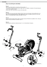
Step 2: Assembling the Front Stabiliser

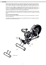
Loosen and remove the transport lock on the front mount of the base frame (1) and then remove the transport 

lock.

Then attach the front stabiliser (40) using four Allen screws M10x20 (108) and four corrugated washers M10 

(112) to the front mount of the base frame (1).

Step 3: Assembling the Pedals

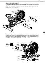
Loosen the screw (109) on the left pedal arm (24). Then insert the thread of the left pedal (38) into the mount of 

the left pedal arm and screw it tight in an anticlockwise direction. Now tighten the screw (109) again. Proceed 

in the same way with the right pedal (39). Make sure that this pedal is tightened in a clockwise direction. The 

pedals are easy to identify because they are marked “R” for right and “L” for left.

Transport Lock 

108

108

112

112

1

40

Summary of Contents for 600354-00019-0001

Page 1: ...AirBike 90PRO ENG I N S TA L L AT I O N O P E R AT I N G M A N U A L...

Page 2: ...25 26 Disposal 26 Notes 27 29 Warranty 30 Service Contract 31 2021 MAXXUS Group GmbH Co KG All rights reserved All rights reserved This publication may not be reproduced stored in a retrieval system...

Page 3: ...should be placed under the device to protect damageable floors such as wood laminates floor tiles etc Please ensure that this underlay cannot slip or slide Do not put this training device on pale or w...

Page 4: ...93 Lock nut M8 3 105 Allen screw M8x30 4 106 Pan head screw M5x12 6 107 Allen screw M6x15 6 No Description QTY 108 Allen screw M10x20 8 109 Allen screw M6x10 4 117 Corrugated washer M10 4 Handlebars S...

Page 5: ...front 1 44 Stabiliser rear 1 51 L Handle left 1 58 R Handle right 1 48 Cockpit frame 1 75 Spacer washer 2 No Description Qty 74 Mounting plate 2 38 L Pedal left 1 39 R Pedal right 1 83 Foot rest 2 84...

Page 6: ...ow the sequence of the installation steps exactly and follow the instructions for the individual assembly steps The installation of the training device must be carried out by responsible adults Carry...

Page 7: ...t of the base frame 1 Step 3 Assembling the Pedals Loosen the screw 109 on the left pedal arm 24 Then insert the thread of the left pedal 38 into the mount of the left pedal arm and screw it tight in...

Page 8: ...the connecting tube 29 of the base frame to the mount at the bottom of the handlebar 58 To do this use the mounting plate right 74 a spacer washer 75 an Allen screw M8x30 105 and a lock nut M8 93 Do n...

Page 9: ...106 Finally attach the bottle holder 118 to the cockpit frame 48 with two pan head screws M5x12 106 Make sure that your exercise equipment is always level In order to compensate for minor bumps or sl...

Page 10: ...in this pulled position and then set the desired saddle height Let go of the knobl to engage the locking mechanism again To do this you may need to move the seat tube slightly up or down to engage the...

Page 11: ...ty Please choose a dry level and warm place to store your training device For your own sake also make sure that you choose a training area which is sufficiently ventilated to ensure optimum oxygenatio...

Page 12: ...ally after 60 to 90 seconds of inactivity Inserting the Batteries The cockpit of your training device is powered by two AA 1 5V batteries To replace or insert the batteries open the battery compartmen...

Page 13: ...n km h RPM indicates the current number of revolutions per minute RPM Power WATT Indication of the power output in relation to the speed in watts WATT Note on calorie measurement The energy consumptio...

Page 14: ...art Press the START key to start training Training End As no target value is set for this program the user has to end the program themselves To do this press the STOP key After 30 seconds the cockpit...

Page 15: ...hreshold 65 or 85 of the maximum heart rate This program can only be used with an optionally available chest belt Step 1 Program Selection Press the Target Heart Rate program key Step 2 Setting the Ta...

Page 16: ...nds the cockpit will switch to stand by mode and after 60 seconds it will automatically switch off General Functions Changing the Display from Kilometres to Miles The display of the distance and speed...

Page 17: ...ill switch to stand by mode and after 60 seconds it will automati cally switch off Interval Training with 20 Second 10 Second Time Intervals Interval 20 10 This HIT training HIT High Intensity Trainin...

Page 18: ...25 carbohydrate and 5 protein Fat burning target zone 60 to 70 of the maximum heart rate This training zone is suitable for athletes and sports people who aim to lose weight Training in this zone the...

Page 19: ...le If the display of the pulse does not work only in individual cases the device is not defective In this case we recommend the use of a chest belt to achieve a permanently correct pulse display This...

Page 20: ...o not just get off your training device immediately the training session is finished Like with the warm up stage you should continue for 3 5 minutes at minimum resistance to cool down After training y...

Page 21: ...ning goals such as weight reduction cardiac exercise training improvement of physical con dition stress reduction etc to strive for training intensity to meet these goals should be be adjusted It make...

Page 22: ...t rate MAXXUS Floor Protection Mats Due to its extreme density and material thickness of 0 5cm these mats provide perfect protection for floors and floor coverings against damaging scratches and soili...

Page 23: ...lay when I turn it on Check if the power cable is both attached correctly to the device and properly plugged into the socket and or if it is damaged Check if the control cable has been pinched or jamm...

Page 24: ...24 Exploded Drawing...

Page 25: ...Holder 1 73 PU Seat 1 74 Fixing Plate 2 75 Disc Spacer 2 76 Cam Handle 1 77 Handle Spacer 2 Part No Description Qty 78 Pressure Plate 1 79 Pressure spring 2 80 Pressure bushing 1 81 Compression Block...

Page 26: ...rn them to the retailer If in doubt please enquire at your municipal or local government authority on how to dispose of your batteries and rechargeable batter ies properly and in an environmentally so...

Page 27: ...27 ENG Notes...

Page 28: ...Notes 28...

Page 29: ...29 ENG Notes...

Page 30: ...eriod for your training device starts on the date of purchase and applies solely to products which were purchased directly from the MAXXUS Group GmbH Co KG or one of the MAXXUS Group GmbH Co KG direct...

Page 31: ...at must be completed Fault Description Please enter a short description of the error as precisely as possible below For example when where and how does the error occur Frequency after which period at...

Page 32: ...Maxxus Group GmbH Co KG Nordring 80 D 64521 Gro Gerau Germany E Mail info maxxus de www maxxus com...

Reviews: