18
Chapter 4 Specification
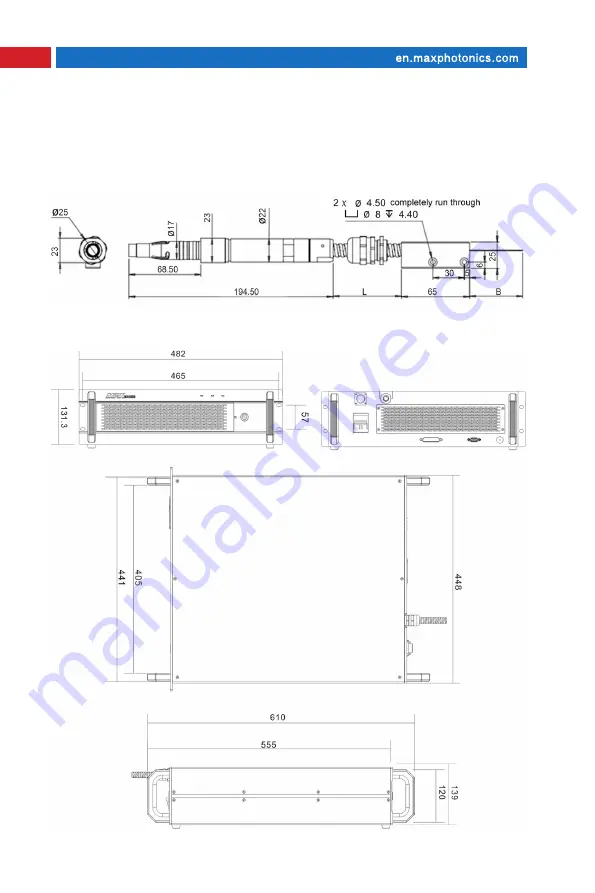
3-Structural Layout
Standard isolated output head dimensions:
(
Unit
:
mm
)
Laser module dimensions:
Page 1: ...MFSQ 150 1500W QCW Fiber Laser Series Maxphotonics Co Ltd...
Page 2: ...rthermore Maxphotonics does not assume responsibility for any infringement of patents or other rights of third parties due to use of the information contained in this document Maxphotonics shall not b...
Page 3: ...ime to read and understand this User s Guide and familiarize yourself with the operating and maintenance instructions before you use the product We strongly recommend that the operator read the Sectio...
Page 4: ...is the second largest domestic fiber laser manufacturer in the domestic market Maxphotonics specializes in the research development production and sales of fiber lasers including pulsed fiber lasers c...
Page 5: ...hapter 3 Product Description 14 1 Features 14 2 Laser Model Designation Codes 15 3 Certification 15 Chapter 4 Specification 16 1 Optical Characteristic Parameters 16 2 General Characteristic Parameter...
Page 6: ...imum Pulse Width And Maximum Frequency Calculation 28 Chapter 6 Service and Maintenance 29 1 Maintenance Notes 29 2 Service Statements 30 Chapter 7 Warranty Statements 31 1 General Items 31 2 Warranty...
Page 7: ...t exhibits unique characteristics that may pose safety hazards Therefore the laser light can t be treated as normal light sources and all operators and people near the laser must be aware of these spe...
Page 8: ...ntil you completely understand and meet the required conditions CAUTION Refers to a potential hazard on product It requires a procedure that if not correctly followed may result in damage to the produ...
Page 9: ...perating the laser and rationally select the safety protective glasses according to the lasing wavelength of the laser If the device is a tunable laser or Raman product it emits light over a range of...
Page 10: ...al power emitted from the primary beam the intensity may be great enough to cause damage to the eyes and skin as well as surface of materials WARNING You must exercise caution to avoid minimize specul...
Page 11: ...then increase the output power gradually when the calibrating and focusing work is done 6 Marking on highly reflective materials is feasible but you must make the laser out of focus or else you may da...
Page 12: ...tage of the laser is the voltage of the normal DC mains and wires are connected accurately Any incorrect wiring method may cause damage to people or instrument Before supplying the power to the device...
Page 13: ...objects and with sufficient airflow to cool the device 3 Before switching on the device make sure that environmental temperature and humidity are within a specified range WARNING Optical damage may r...
Page 14: ...ease refer to the list below Laser Institute of America LIA 13501 Ingenuity Drive Suite 128 Orlando Florida 32826 Phone 407 380 1553 Fax 407 380 5588 Toll Free 1 800 34 LASER American National Standar...
Page 15: ...Devices and Radiological Health 21 CFR 1040 10 Performance Standards for Light Emitting Products US Department of Labor OSHA Publication 8 1 7 Guidelines for Laser Safety and Hazard Assessment Laser S...
Page 16: ...n that can be integrated directly into the user s device Low power consumption practical and durable design for laboratory and market applications Main Features 1 High beam quality 2 Alternative the l...
Page 17: ...nation Codes 3 Certification Maxphotonics certifies that this equipment has been thoroughly tested and inspected and meets published specifications prior to shipping Upon receiving your equipment chec...
Page 18: ...wer 10 100 6 Modulation Rate 1 5000 Hz 7 Pulse Width 0 05 50 ms 8 Duty cycle range 0 50 9 Emission Wavelength 100 CW 1070 1080 1090 nm 10 Optical efficiency 10 100 linear fitting 65 11 Whole Machine E...
Page 19: ...Ambient Temperature 10 40 4 Operating Ambient Relative Humidity 10 85 5 Cooling Method Air cooling 6 Storage Temperature 10 60 7 Dimensions 510 5 448 131 5mm D x W x H Without Handle mm 8 Weight 34 k...
Page 20: ...18 Chapter 4 Specification 3 Structural Layout Standard isolated output head dimensions Unit mm Laser module dimensions Unit mm...
Page 21: ...Pin No Pin definition Pin direction Pin level Remarks 1 Digitally D_COM D_COM 2 Red light D_INPUT 24V High Open red low Off red 3 Emergency stop D_INPUT 24V H i g h S t o p L o w N o t connected norma...
Page 22: ...tic ring to the external control line which will have a certain anti interference effect 3 Front Panel Indicator Color ACTIVE light Green laser on No light the laser is not turned on ALARM light Red L...
Page 23: ...Waveform Editing When using the internal control mode the waveform editing function plays the role of waveform editing the pulse shape editing is set by the control software as shown in Figure 3 The p...
Page 24: ...eously Click Select Waveform Download to send the waveform pattern of the corresponding selected display to the laser otherwise the current laser waveform is displayed 2 Equipment information Mark the...
Page 25: ...alarm Please check whether the fan is normal whether it is blocked by dust or other things and there is a temperature alarm turn off the laser and still have an alarm for cooling for a period of time...
Page 26: ...external control energy of the laser is set high 8 QBH indicates that the laser QBH head is not installed in place NOTES All the above status information is gray when the laser is running normally Whe...
Page 27: ...m of the laser is completed using the waveform editing interface as shown in Figure 3 The laser can store 16 sets of waveforms Before storing the waveform first perform waveform number selection to se...
Page 28: ...ode uses the 21 and 22 pins of DB25 to turn on off the laser ie Laser_on interface the laser power uses the power set by the internal control software 5 External control analog pulse In the external c...
Page 29: ...s mode the laser is switched to use the DB25 21 and 22 pins that is the laser_on interface continuous power control uses the DB25 23 and 25 pins namely the external control analog interface 10V repres...
Page 30: ...1000 Current peak power W The following is an example of the maximum pulse width corresponding to different peak power 2 Maximum frequency Hz maximum average power 150W Current pulse energy J The fol...
Page 31: ...tive after finding the faults Upon receiving our authorization you need to pack the product in a suitable package and return it You should keep the proof when finding any damage after receiving the pr...
Page 32: ...e reading this User Guide carefully and flowing the operation steps stictly Please call the Customer Service Department for other questions Your problems will be follow up by our technical support gro...
Page 33: ...replace the products with faults caused by its material or production technology within the warranty period and repairs or replacement of all the products within the warranty scope are carried out ac...
Page 34: ...the warranty scope Customers are obligated to understand the information above and operate according to the User Guide and specification or the faults arising therefrom are not included in the warrant...