


maxon motor control
4-22
Document ID: rel4270
EPOS2 Positioning Controller
Edition: December 2013
EPOS2 70/10 Hardware Reference
© 2013 maxon motor. Subject to change without prior notice.
4.5
Encoder Connector (J4)
Best Practice
The use of encoder with built-in line driver is mandatory.
Even though 2-channel will do, we strongly recommend to use only 3-channel versions!
Implemented are three high-speed RS422 receivers featuring fault detection circuitry and fault status
outputs. The receivers’ inputs feature fault thresholds that detect the device’s “not in valid state”.
The receivers indicate whether a receiver input is in open circuit condition (except index channel), short-
circuit condition, or beyond the common mode range (smaller -10 V or 13.2 V). They also gener-
ate a fault indication if the differential input voltage drops below the 475 mV threshold.
By default, the controller is set for a 500 count per turn encoder. For other encoders, you will need to
adjust respective settings via software.
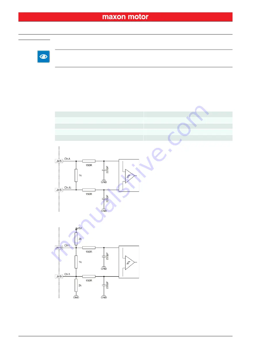
Figure 4-10
Encoder Input Circuit for Channel A (analogously valid also for Channel B)
Figure 4-11
Encoder Input Circuit for Index Channel
Encoder supply voltage
+5 VDC
Max. encoder supply current
100 mA
Min. differential Input voltage
± 475 mV
Line receiver (internal)
EIA RS422 Standard
Max. encoder input frequency
5 MHz


