MAXIDRY MAXIMD200 Installation Manual Download Page 51

113274 - 1

47

SECTION VII

COMPONENT SYSTEM DESCRIPTIONS

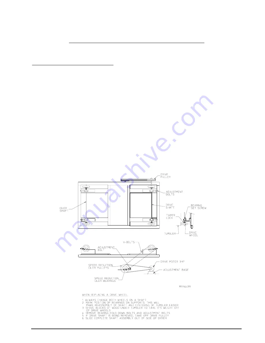
A. TUMBLER DRIVE SYSTEM

The tumbler is supported and driven by four (4) 11-inch diameter drive wheels.  Two (2) of these wheels are
attached to a 1-1/2” diameter idler shaft, while the other two (2) are attached to a 1-1/2” diameter drive shaft.
Each of the wheels is fastened to the shafts by a taper lock bushing.  The taper lock is made up of three (3)
pieces: an inner collar, an outer sleeve, and a key.  The inner and outer elements have matching opposing tapers.
As a result, when the bolts are tightened, the taper lock contracts onto the shaft and expands into the drive wheel
hub locking the wheel onto the shaft.

The idler shaft and drive shaft are each supported by two (2) 1-1/2” diameter pillow block bearings.  These
bearings sit on slotted support channels and can be moved inward or outward by the adjustment bolts to raise or
lower the tumbler.

The drive system consists of a shaft mounted pulley, two (2) V-belts, and a 3 hp (2.24 kW) drive motor.  Belt
tension can be adjusted by tightening or loosening the gear reducer turnbuckle.

TUMBLER DRIVE SYSTEM

Summary of Contents for MAXIMD200

Page 1: ...ne pouvez rejoindre le fournisseur de gaz appelez le service des incendies L installation et l entretien doivent tre assur s par un installateur ou un service d entretien qualifi ou par le fournisseur...

Page 2: ..._____________________________________________ MAXIMD200 IMPORTANT NOTE TO PURCHASER Information must be obtained from your local gas supplier on the instructions to be followed if the user smells gas...

Page 3: ...OMTHEMACHINETOALLOWACCESSFORCLEANING ADJUSTING INSTALLATION OR TESTING OFANYEQUIPMENT PER OCCUPATIONALSAFETY ANDHEALTHADMINISTRATION OSHA STANDARDS CAUTION DRYERSSHOULDNEVERBELEFTUNATTENDEDWHILEINOPER...

Page 4: ...ryer must never be operated with any of the back guards outer tops or service panels removed PERSONAL INJURY OR FIRE COULD RESULT IMPORTANT Dryer must be installed in a location environment which the...

Page 5: ...14 C Fresh Air Supply Requirements 15 D Exhaust Requirements 16 E Compressed Air Supply System 22 F Electrical Information 24 G Gas Information 28 H Water Supply Connection For Sensor Activated Fire...

Page 6: ...48 C Air Blower Drive System 48 D Safety Devices 48 E Steam Damper Actuator System 50 SECTION VIII MANUAL RESET BURNER HI LIMIT INSTRUCTIONS 51 SECTION IX DATA LABEL INFORMATION 52 SECTION X PROCEDUR...

Page 7: ...epted but the number received and the number refused must be noted on the receipt 4 If you determine that the dryer was damaged after the trucker has left your location you should call the delivering...

Page 8: ...ely call your gas supplier from a neighbor s phone Follow the gas supplier s instructions f If you cannot reach your gas supplier call the fire department 4 Installation and service must be performed...

Page 9: ...e dryer as soon as the drying cycle has been completed WARNING Articlesleftinthedryerafterthedryingandcoolingcycleshavebeencompletedcan create a fire hazard 12 DO NOT operate steam dryers with more th...

Page 10: ...IR CONNECTION COMPRESSED AIR VOLUME OVEN SIZE kW Btu hr kcal hr VOLTAGE AVAILABLE 208 575V 3 3 4w 50 60 Hz APPROX NET WEIGHT 3 625 lb 1 644 27 kg APPROX SHIPPING WEIGHT 3 891 lb 1 764 93 kg AIRFLOW 6...

Page 11: ...113274 1 7 B DIMENSIONS AND COMPONENT LOCATION NON TILT GAS MODEL...

Page 12: ...8 113274 1 NON TILT STEAM MODEL...

Page 13: ...Gas or CAN CGA B149 2 M91 Liquid Propane Gas or LATEST EDITION for General Installation and Gas Plumbing or Canadian Electrical Codes Parts 1 2 CSA C22 1 1990 or LATEST EDITION for Electrical Connecti...

Page 14: ...10 113274 1 1 Reassembly Instructions For Gas Dryer Shipped In Two 2 Pieces...

Page 15: ...at the bottom of the right tumbler section b Pull the tumbler section power cable up from the left side of the base through the hole in the bottom of the tumbler section Reconnect the wires of this c...

Page 16: ...12 113274 1 2 Reassembly Instructions For Steam Dryer Shipped In Two 2 Pieces...

Page 17: ...16 cm tumbler junction box located at the bottom of the tumbler section Refer to the illustration on the previous page c Drop the control cable connector from the rear right side of the tumbler sectio...

Page 18: ...s dryer and the ceiling A ceiling height of 120 inches 304 8 cm is required for gas dryers and a ceiling height for 130 inches 330 2 cm is required for steam dryers The dryer must be leveled for prope...

Page 19: ...quired for each gas dryer and a minimum of 8 square feet 0 74 square meters for each steam dryer To compensate for the use of registers or louvers used over the openings this make up air area must be...

Page 20: ...HAUSTED COMMON DUCTWORK IS NOTACCEPTABLE The exhaust ductwork should be laid out in such a way that the ductwork travels as directly as possible to the outdoors with as few turns as possible Single or...

Page 21: ...ches 60 96 cm round duct 464 square inches 2 993 square centimeters duct must be used The horizontal or vertical duct total run on gas models must not exceed 50 feet 15 24 meters and steam models must...

Page 22: ...18 113274 1...

Page 23: ...113274 1 19...

Page 24: ...20 113274 1...

Page 25: ...w at least twice the diameter of the duct between the duct opening and nearest obstruction IMPORTANT DO NOT use screens louvers or caps on the outside opening of the exhaust ductwork NOTE Exhaust back...

Page 26: ...n size is 1 8 N P T No air filtering or pressure regulating devices are provided with the standard non tilt dryer 1 CompressedAir Supply Connection Location For Non Tilt Dryers a Gas Dryers The air li...

Page 27: ...113274 1 23 b Steam Dryers The air line supply connection is made into the 1 8 N P T tee which is located at the left hand side of the top of the dryer Refer to the illustration below...

Page 28: ...ON or in Canada the Canadian Electrical Codes Parts 1 2 CSA C22 1 1990 or LATEST EDITION IMPORTANT Failure to comply with these codes or ordinances and or the requirements stipulated inthismanualcanre...

Page 29: ...0 240 VAC ARE NOT THE SAME When ordering specify exact voltage When fuses are used they must be dual element time delay current limiting class RK1 or RK5 ONLY Calculate determine correct fuse value by...

Page 30: ...C ARE NOT THE SAME When ordering specify exact voltage When fuses are used they must be dual element time delay current limiting class RK1 or RK5 ONLY Calculate determine correct fuse value by applyin...

Page 31: ...f these codes grounding must conform to applicable requirements of the National Electrical Code ANSI NFPA NO 70 LATEST EDITION or in Canada the installation must conform to applicable Canada Standards...

Page 32: ...NG FIRE OR EXPLOSION COULD RESULT 1 Gas Supply The gas dryer installation must meet the American National Standard National Fuel Gas Code ANSI Z223 1 LATESTEDITION or in Canada the Canadian Installati...

Page 33: ...so that the gas pressure must be regulated upstream of the dryer The pressure measured at the gas valve pressure tap must be a consistent 10 5 inches 26 1 mb water column There is no regulator or regu...

Page 34: ...BTUs being supplied The dryer is provided with a 1 1 4 N P T inlet pipe connections extending out of the top of the burner box The minimum pipe size supply line to the dryer is 1 1 2 N P T For ease of...

Page 35: ...149 1 M91 Natural Gas or CAN CGA B149 2 M91 Liquid Propane Gas or LATEST EDITION for General Installation and Gas Plumbing as well as local codes and ordinances and must be done by a qualified profess...

Page 36: ...to limit the acid attack of the steam coils IMPORTANT CoilfailureduetoimproperpHlevelwillVOIDTHEWARRANTY 2 Steam Requirements High Pressure Inlet 2 supply line connection Return 2 return line connect...

Page 37: ...ns d Shutoff valves for each dryer should be installed in the supply return and drip trap return lines This will allow the dryer to be isolated from the supply and return mains if the dryer needs main...

Page 38: ...T c No air regulation is provided with a standard dryer External regulation filtration of 80 PSI 5 51 bar must be provided It is suggested that a filter regulator gauge F R G arrangement be added to t...

Page 39: ...oviding instant heat to start the drying process When the damper is closed ambient air is drawn directly into the tumbler allowing a rapid cool down Diagram 1 shows the damper in the heating open mode...

Page 40: ...Flow Control Operation Adjustment Steam damper operation was tested and adjusted prior to shipping at 80 PSI 5 51 bar If steam damper adjustment is necessary locate the flow control valve and make the...

Page 41: ...eled and go toWrinkle Guard 7 When the programmed drying time has expired the Phase 7 Non Coin microprocessor controller computer will proceed into the Cool Down Cycle mode 8 Once the Cool Down Cycle...

Page 42: ...When the dryer is first started during initial start up the burner has a tendency not to ignite on the first attempt This is because the gas supply piping is filled with air so the dryer may have to b...

Page 43: ...oprocessor controller computer has been preprogrammed by the factory with the most commonly used parameter programs selections If computer program changes are required refer to the computer programmin...

Page 44: ...ust be performed 1 Discontinue power to the dryer either at the external disconnect switch or the circuit breaker 2 Discontinue the heat supply a GAS MODELS discontinue the gas supply 1 SHUT OFF exter...

Page 45: ...contacting the Service Department be sure to give them the correctmodel number and serialnumbersothatyourinquiryishandledinanexpeditiousmanner B PARTS 1 Replacement parts should be purchased from the...

Page 46: ...tact the reseller from whom you purchased the equipment and request a dryer warranty form NOTE Whenever contacting the factory for warranty information be sure to have the dryer smodel numberand seria...

Page 47: ...packaged to insure that they are not damaged in transit Damage claims are the responsibility of the shipper IMPORTANT No replacements credits or refunds will be issued for merchandise damaged in trans...

Page 48: ...rage usage which is considered six 6 to eight 8 operational running hoursperday IMPORTANT Dryer produces combustible lint and must be exhausted to the outdoors Every 6 months inspecttheexhaustductinga...

Page 49: ...m coil fins be careful not to bend the fins If fins are bent straighten by usingafincomb whichisavailablefromlocalair conditioningsupplyhouses Inspect and remove lint accumulation in customer furnishe...

Page 50: ...otor contactors and overloads are tight This is done to accommodate the compression of the wires over time C LUBRICATION MONTHLY The two 2 bearings that support the impellor fan shaft must be lubricat...

Page 51: ...e inner and outer elements have matching opposing tapers As a result when the bolts are tightened the taper lock contracts onto the shaft and expands into the drive wheel hub locking the wheel onto th...

Page 52: ...the dryer will tilt If the dryer is started when the load doors are open the microprocessor controller computer light emitting diode L E D display will show front door not closed or rear door not clos...

Page 53: ...he burner boxes and the display will read an error code of Burner Hi Limit Fault The thermostat must be manually reset and the Phase 7 computer must be reset 5 Sail Switch for Gas Dryers Only The sail...

Page 54: ...m the solenoid valve so that the solenoid valve blocks the air supply to the pistons and the air in the pistons is bled to the atmosphere The springs in the pistons now retract the piston rods closing...

Page 55: ...ay the same error code described above along with an audio indication If the drum temperature is above 100 F 38 C the dryer will continue to run with no heat for 3 minutes or until the drum temperatur...

Page 56: ...Allows the manufacturer to gather information on your particular dryer 3 Type of Heat This describes the type of heat for your particular dryer gas either natural gas or L P gas electric or steam 4 H...

Page 57: ...dy L E D indicator indicates normal operation No L E D indicator indicates a power or an internal failure has occurred 2 For Models with DSI Module Type II Theory of Operation Start the drying cycle W...

Page 58: ...jet s remain on for 2 minutes and will automatically activate again if a fire condition remains or reignites While the water jet s are activated the tumbler will jog to move the water throughout the...

Page 59: ...er solenoid valve is a 1 2 M P T the S A F E system must be supplied with a minimum water pipe size of 1 2 inch and be provided with 40 PSI 2 75 bar and a maximum of 100 PSI 6 89 bar of pressure For u...

Page 60: ...e the minimum 1 2 inch supply feed line Flexible supply line coupling must be used in effort to avoid damage to electric water solenoid valve WARNING Water must be supplied to sensor activated fire ex...

Page 61: ...ted in an area where it will be exposed to cold freezing temperatures provisions must be made to protect these water lines from freezing WARNING If the water in the supply line or water solenoid valve...

Page 62: ...trip point if so water will remain on The control will continue to check if temperature is above trip point every 30 seconds If the water has been on for a constant 10 minutes the water will be turned...

Page 63: ...WITCH CLOSED FAULT Sail switch is closed should be open at the start of a cycle SAIL SWITCH OPEN FAULT Sail switch remained open after the cycle started Should have closed BURNER HIGH LIMIT FAULT Burn...

Page 64: ...Part No 113274 1 05 17 11...

Reviews: