Page 6 of 10
ARF U-control Profile
S141208
c)
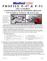
Cut or drill an opening through the wing’s center section for your flap coupler.
d)
Fit the coupler through the wing’s center section and use epoxy to secure
the flap coupler into the flaps.
e)
Use thin CA adhesive to secure the flaps to the wing.
FUSELAGE –
1.
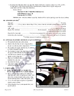
Test-fit both sides of the main landing gear struts into their slots on
the sides of the fuselage. Secure these main gear struts to the fuselage
with 8 ea. 10mm by 3mm wood screws and 4 ea. mounting straps,
then secure the wheels to the main gear with wheel collars.
2.
If you are using a glow engine:
a)
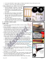
Test fit your engine centered in the mount and orient the
muffler below the cylinder. If necessary, sand or trim the
space between the engine mounting rails to fit your engine.
Mark and drill mounting holes for your engine. Apply epoxy
to fuel proof all exposed/raw wood.
b)
Use mounting bolts, washers and self-locking nuts (not
supplied) to secure your engine to the fuselage.
c)
Assemble your fuel tank’s vent and clunk lines in the
stopper and secure the stopper in your fuel tank’s opening.
d)
Test fit your fuel tank on the side of the fuselage opposite
the cylinder head. We recommend you cut a 1/4- to 1/ 2-
inch thick piece of scrap foam rubber to insert between the
fuselage and the fuel tank to minimize foaming (not
included).
e)
Choose whether to hold the fuel tank in position with nylon
cable ties, or to use J-bolts and rubber bands (not included).
Drill your mounting holes where the fuselage’s wood is
solid and install the fuel tank as shown in the photos on the
next page.
f)
Install your engine’s muffler and attach the clunk and vent lines to the tank. Route the lines through the
nose and attach them to your engine’s carburetor and muffler’s pressure nipple.
3.
If you are using an electric power system:
(NOTE: Your motor needs a minimum power rating of 400 Watts; we recommend using 3S or 4S Lipo
batteries and a motor controller rated at approx. 60 amps.)
a)
To mount an electric motor to your P-47’s or P-51’s nose you need: 2 ea. 3/4-inch wide by approx.
2 3/4-inch long pieces of aluminum L-channel, 4 ea. #6 x 3/4-inch bolts,
4 ea. matching nuts, threadlock compound, hook-and-loop material and
the mounting hardware supplied with your motor.
b)
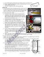
Clamp the two pieces of L-channel together and drill four 3/16-inch
diameter holes through their ‘back-to-back’ mating surfaces in a
rectangular pattern measuring approx. 2 inches tall by 1/2-inches wide,
as shown at the right. Mark the pair of L-channels to identify their
matching ‘back-to-back’ holes.
c)
Position the two pieces of L-channel with one on each side of the fuselage
at the front of the vertical surface in the space between the glow engine
beam mounts. Using the ‘back-to-back’ holes you drilled as a guide, drill
four 3/16-inch holes through the fuselage. Using the guide holes and 4 #6
2
3/4
inches
2
inches
1/2
inch
Pattern for
drilling both
aluminum
L-channel’s
back-to-back
holes
Wire flap coupler
(not included)
Sample fuel tank mounting options


