Page 7 of 10
ARF U-control Profile
S141208
x 3/4-inch bolts and 4 ea. matching nuts, secure the two pieces of L-channel to the fuselage. Apply
thread-locking compound to secure the 4 ea. bolts and 2 ea. pieces of L-channel to the nose.
d)
Test fit your motor and its mounting hardware to the two
forward-facing surfaces of the two pieces of L-channel.
Mark where holes are needed to mount your motor to the
L-channel. (NOTE: Depending on the outer diameter of
your motor, it may be necessary to increase the space
between the glow engine’s mounting rails. If so, we
recommend using a high speed motor tool with a sanding
drum, or you could use a course file and sandpaper.)
e)
Drill the motor-mounting holes in the L-
channels’ forward-facing surfaces. Attach
your motor to the L-channel with hardware
provided by the maker of your motor. Use
threadlock compound to secure the motor to
the front faces of the two pieces of L-
channel.
f)
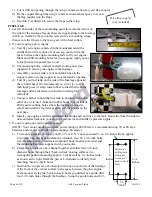
For safety, we recommend you add a little
foam rubber at the front of each battery.
g)
To optimize the balance of your P-47 or
P-51, we recommend mounting a battery on
each side of the fuselage in a series or
parallel configuration, depending on the
power requirements of your motor. As
shown at the right, make sure your batteries
are safely attached to the fuselage with
hook-and-loop material (not included).
4.
Slide the wing’s center section into its mounting
grooves in the fuselage and secure the wing to
the fuselage with wood screws.
(NOTE: If being able to remove the wing
from the fuselage is not a feature you value,
you may permanently attach the wing to the
fuselage with epoxy.)
5.
When setting up an electric power system and
using a radio receiver for throttle control, wrap
the receiver in foam rubber (not included) and
position the receiver inside the equipment bay
in the right side of the wing. Use small wood
screws to attach the hatch covers.
6.
Guide the free end of each leadout wire through
a crimp tube, through the hole in the end of the bellcrank, then
back through the crimp tube. Adjust the leadout wires to the
same length and ajust the size of the resultant loop as shown at
the right.


