background image


(Note: As you press the lower wing panels firmly against the fuselage, 
carefully align the lower wing panel’s dowel pins with the
in the fuselage.) 
 

7.


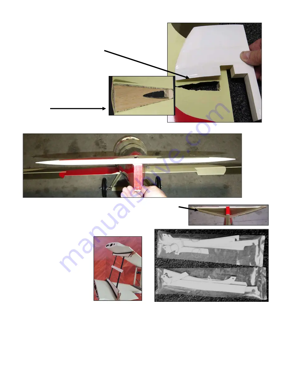
Cut away the Mylar covering the slotted 
opening in the horizontal stabilizer for the 
vertical stabizer and test-fit the vertical 
stabilizer to the horizontal stabilizer. 
 

8.


Test fit the horiz. stabilizer to its platform 
at the top-rear of the fuselage. Remove the 
Mylar at the bottom of the horiz. stabizer 
to ensure a good wood-to-wood glueing 
surface between the horiz. stabilizer and 
the fuselage. 
 

9.


To ensure the horizontal stabilizer is parallel to the lower wing
visually compare the lower wing to the horizontal stab


10.


Secure the horiz. stab. to the fusealge with 
to hold the horiz. stab. parallel to the lower wing 

11.


Identify two identical plastic packets contain
supports which help to ensure the wings, struts and wing wir
may be safely transported and stored when removed 
Nieuport 28. 

12.


As shown at the right, 
test-fit the parts of the 
two sets of wooden 
wing supports. 

13.


Glue the wooden wing   
supports together with   
epoxy or aliphatic resin. 
 
(Note: As shown above, when 
completed, each supports’ 
curved wooden surface rests against and supports
bands or string to secure the wing supports to the

14.


Securely glue the metal joiner into the each half of the elevator. 

15.


After the epoxy used to secure the horizontal stabilizere
to the horizontal stabilizer. 

16.


Guide the end of the elevator pushrod through the fuselage out of its opening. Test fit a 

Copyright 20


Page 6 of 16


As you press the lower wing panels firmly against the fuselage,   

lign the lower wing panel’s dowel pins with their openings 

for the 


is parallel to the lower wing, 

the lower wing to the horizontal stabilizer. 

Secure the horiz. stab. to the fusealge with 30 minute epoxy. Use masking tape   

lower wing until the epoxy is fully cured. 

packets containing all the parts for the wooden wing   

ensure the wings, struts and wing wires   

when removed from your   

rests against and supports the bottom of the top wing and the top of the bottom wing.

ecure the wing supports to their wing panels.) 

lue the metal joiner into the each half of the elevator.   

e horizontal stabilizere to the fuselage has fully cured, use CA hinges to 

rough the fuselage out of its opening. Test fit a control horn assembly to the elevator. 

Copyright 2020 - N28 / RS051120


top of the bottom wing. Use rubber 

use CA hinges to attach the elevator 

control horn assembly to the elevator. 

Summary of Contents for NIEUPORT 28 ARF

Page 1: ...on By the time the Nieuport 28 became available in early 1918 it was already considered surplus from the French point of view Their SPAD XIII was a superior aircraft in most respects and had already become firmly established as the standard French fighter A 1 5 www maxfordusa com When the Nieuport 28 was offered to the United States it was immediately accepted by the American Expeditionary Force n...

Page 2: ...lt in an unsafe or unworkable model In a few cases the instructions may differ slightly from the photos in those instances the written instructions should be considered as correct If you have a question or concern about these instructions before you proceed with assembly of this product contact your dealer or speak to a Maxford USA customer service representative at 562 529 3988 AM to 5 PM Pacific...

Page 3: ...lways check each clevis before and after each flight fiberglass or carbon fiber reinforced parts If you drill fiber reinforced part always wear safety goggles a particle mask and rubber gloves to guard yourself from eye skin and respiratory tract irritation iberglass or carbon fiber dust the dust may blow back into your face Check the Mylar covering material s joints and surfaces if necessary care...

Page 4: ... that is accepted by Maxford USA for credit is subject to a 10 to 20 restocking fee the final amount will be determined by Maxford USA upon receipt and examination of the returned merchandise Mfg Inc 0 Print the RMA issued by Maxford USA on the package near the address PECIAL FEATURES OF THIS NIEUPORT 28 MODEL painted matte color no more shinning mylar from the fuselage owl with system for your is...

Page 5: ...nt corners 6 Slide the lower wing s spar midway through the fuselage then temporarily position the left and right lower wing panels onto the lower wing s spar Copyright 20 Page 5 of 16 with this Nieuport 28 upper and lower wing panels and upper wing s center section vertical and horizontal stabilizers rudder and elevator halves with all hinge openings precut Prepainted and pretrimmed fiberglass co...

Page 6: ...leted each supports curved wooden surface rests against and supports bands or string to secure the wing supports to the 14 Securely glue the metal joiner into the each half of the elevator 15 After the epoxy used to secure the horizontal stabilizere to the horizontal stabilizer 16 Guide the end of the elevator pushrod through the fuselage out of its opening Test fit a Copyright 20 Page 6 of 16 As ...

Page 7: ...ly hold the rudder in a neutral straight ahead position Slide a crimp tube onto each of the rudder s pull pull cables Guide the end of the cable through the holes in the rudder s control horns Draw the pull pull cables snug then guide the end of each Copyright 20 Page 7 of 16 Drill a hole in the elevator and mount the elevator control horn to the elevator Attach the elevator pushrod to the elevato...

Page 8: ...you may use the preinstalled string to PULL the servo wire extension through the wing however you might find it easier to use masking tape to temporarily attach each extension s female connector to the end of a length of straight coat hanger wire then use the coat to PUSH the extension s connector through the wing and into the wing panel opening for each aileron servo Copyright 20 Page 8 of 16 Cut...

Page 9: ...h clevis with a short hole hole in each aileron install the aileron attach the clevis on the loose end of the aileron control horn Remove the masking tape from the ailerons the clevises are adjusted coat each clevis and rod with safely affix each clevis to its rod also as a safety clevis before and after each flight 44 Using wood screws attach two wing wire anchors edge and the second near the tra...

Page 10: ... warp the wings Note For clarity the wing panel at the right Copyright 20 Page 10 of 16 inch from the root rib at the trailing edge for these wing wire anchor screws Point of each wing wire anchor away from the fuselage as you tighten these ailerons Slide the left and right pairs of wing panels away from the fuselage and from the the servo extension wires inside the slide the pairs of wing panels ...

Page 11: ... mounting box s firewall for the engine s or motor s required openings such as motor wires ignition leads throttle servo mounting and or pushrods etc 61 Secure your engine or motor to the engine box motor s supplied hardware T nuts mounting bolts standoffs washers etc are using a 90 to 120 sized glow engine use particular engine not included If you install Copyright 20 Page 11 of 16 through all an...

Page 12: ...d is permanently anchored with 71 Test fit the dummy engine inside the cowl and use backplate as a guide to make an opening in the center Copyright 20 Page 12 of 16 lectric motor s supplied mounting hardware to attach your motor to the included Electric power system batteries may be attached on either side or at the top and bottom of the engine mounting box some batteries might fit through the coc...

Page 13: ... 76 If you are installing the optional machine guns free the machine gun mounts from their molding flash then drill guide holes and use wood screws and epoxy to attach a gun to each mount A adhesive around the base of each mount and the fuselage until the glue is fully set 77 Install your radio equipment and make any necessary adjust ments to servo control throws including the engine s throttle ki...

Page 14: ... the included presliced cockpit coaming around the edge of Congratulations Assembly is finished he Nieuport 28 s center of gravity CG within 3 5 8 to 3 7 8 inches back from the leading edge of the top wing If necessary move batteries and or add weight to the nose or tail to ensure the CG is correct shrink covering material s joints and surfaces if necessary carefully use a dedicated cover and heat...

Page 15: ...tubes b Remove and set aside the wing transport crutch assemblies and the two wood screws stored in their CA reinformed openings in the lower wing panels c Reconnect the aileron extension wires to the Y cable reattach the servo extension safety clips and neatly dress the wires inside the wing or fuselage d Carefully position the plastic wing landing gear retainer onto the outer surface of the lowe...

Page 16: ...Y SAFELY Designed and distributoed by Maxford USA RC Model Distribution Inc 13630 Imperial Hwy 11 Santa Fe Springs CA 90670 Telephone voice 562 529 3988 Website www maxfordusa com Order replacement parts servos batteries gas engines brushless motors electronic speed controls and a wide variety of other high quality RC hobby items online at www maxfordusa com ...

Reviews: