52.
After the wing wires have been routed through all
a final set of threaded brass rods and clevises
53.
Cut and remove the excess wire. Adjust the clevises to
54.
With the wing wires positioned and the tension
adjusted, secure each wing wire by ‘snugging’ the brass
rod’s lock nut against its clevis, then secure
clevis by applying epoxy or CA adhesive onto the rod’s
threads at each nut and inside each clevis.
55.
Use the predrilled holes in each half of the elevator to attach
control-horn assemblies. Use CA adhesive, the supplied CA
hinges and the precut hinge slots to attach the two halves of
the elevator to the horizontal stabilizer.
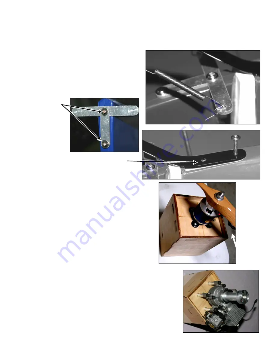
56.
Use two screws to
attach the tail-wheel
tiller to the rudder.
Harden the holes in the
bottom of the rudder
with CA adhesive, then
add a little CA at the
area where the tiller bar
touches the bottom of
the rudder.
57.
As shown at the right, use two screws to attach the tail
assembly to the platform in the bottom of the fuselage.
Apply CA adhesive to harden the holes where these screws
are inserted.
58.
Position a coil spring on each end of and between the
T-bracket and the tail-wheel’s steering arm. Hold
and tail wheel in a neutral/straight-ahead postion and bend the
ends of the springs to adjust their lengths to align the
tail-wheel’s direction with the rudder. Wind both the ends of
each spring around the T-bracket and the tail
arm to secure the springs.
NOTE
:
Since there are no industry standards for engine mounts,
RC-radio features, nor the varied personal preferences of
model airplane owners and pilots, the following
system installation steps are generalized –
make adjustments in accordance with your particular engine,
motor, radio equipment and favored flying style. If you
require assistance, call us or the maker of your engine, motor or radio, or call upon your local RC club’s instructor or WWI
warplane ‘guru.’
59.
To utilize the engine box’s built-in down and right thrust
motor so its propeller’s backplate is in line with the intersecting lines drawn on the
engine mounting box’s firewall. If you install an electric power system
motor onto the supplied engine-mounting box as
60.
Once you determine your engine’s or motor’s
mounting box’s firewall for the engine’s or motor’s
required openings (such as motor wires, ignition leads, throttle servo mounting
and/or pushrods, etc.).
61.
Secure your engine or motor to the engine box’
motor’s supplied hardware (T-nuts, mounting bolts, standoffs, washers, etc.
are using a 90- to 120-sized glow engine, use
particular engine (not included). If you install
Copyright 20
Page 11 of 16
through all anchor points (1 through 8), secure the end of each wing wire by
final set of threaded brass rods and clevises at anchor points 4 and 8 at the top of each cabane strut
Adjust the clevises to ‘snug’ the wing wires.
tension equally
adjusted, secure each wing wire by ‘snugging’ the brass
secure each rod to its
CA adhesive onto the rod’s
Use the predrilled holes in each half of the elevator to attach
horn assemblies. Use CA adhesive, the supplied CA
hinges and the precut hinge slots to attach the two halves of
attach the tail-wheel
assembly to the platform in the bottom of the fuselage.
CA adhesive to harden the holes where these screws
Position a coil spring on each end of and between the
wheel’s steering arm. Hold the rudder
ahead postion and bend the
ends of the springs to adjust their lengths to align the
wheel’s direction with the rudder. Wind both the ends of
bracket and the tail-wheel’s steering
Since there are no industry standards for engine mounts,
radio features, nor the varied personal preferences of
following power
you are invited to
make adjustments in accordance with your particular engine,
motor, radio equipment and favored flying style. If you
require assistance, call us or the maker of your engine, motor or radio, or call upon your local RC club’s instructor or WWI
down and right thrust, test-fit your engine or
is in line with the intersecting lines drawn on the
If you install an electric power system, mount the
mounting box as pictured at the right.
or motor’s correct position, drill holes in the
or motor’s mounting bolts, and any other
ignition leads, throttle servo mounting
to the engine box’s firewall using the engine’s or
nuts, mounting bolts, standoffs, washers, etc.). If you
use an engine mount sized to fit your
install an electric power system, use your
Copyright 2020 - N28 / RS051120
each wing wire by installing
cabane strut.
require assistance, call us or the maker of your engine, motor or radio, or call upon your local RC club’s instructor or WWI


