Copyright 2013: Maxford USA
Page
Blériot XI: S130926
21.
Use a total of four approx.
5/16
-inch long (1 cm) screws to attach
loosely the upper wing-wire-mounting braces in the guide holes
at the upper corners of the front surfaces of the fuselage
formers.
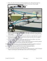
22.
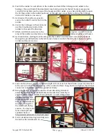
Insert the approx. 4
3/4
-inch metal rod through the holes in the
upper ends of the upper wing-wire-mounting braces. As shown
below, position the nuts, clips, swivels, springs and self-locking
nuts on the metal rod between each pair of braces.
23.
Securely tighten the nuts against the self locking nuts on the
upper wing-wire-mounting braces and the four screws into the
fuselage formers.
24.
Mount a propeller onto your motor and test-fit your motor and
its mounting hardware aligned at the intersecting lines on the
front former of the fuselage.
NOTE: The locations of your Blériot XI’s motor, landing gear and
dummy engine will not be finalized until after any/all items that
add weight behind the center of gravity have been installed.
Then, to transfer weight forward, spacers may be added be-
tween your motor and the fuselage’s front former and the
landing gear can be moved forward. (See section VII #1
on page 15.)
25.
Temporarily attach your motor to the front
former of the fuselage; as noted above, do NOT
permanently mount your motor to the front
former at this time.
26.
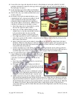
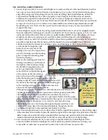
Slide the main landing
gear’s mounting arms into
the slots in the fuselage’s
front former.
27.
Move the landing gear forward or backward
inside the nose to position the front surfaces of
the landing-gear assembly approx.
1/4
-
to
1/2
-
inch behind the back surfaces of the propeller
blades.
28.
Solder any required connectors to your motor, electronic speed
control (ESC) and battery.
29.
Test-fit your ESC and battery as far forward inside the fuselage
as you can to help your CG.
30.
Guide the motor’s three power wires into the fuselage and
connect the motor to the ESC. Guide the ESC’s battery connector
toward the battery tray and guide the ESC’s servo-type
connector into the cockpit in front of the rudder and elevator
servos.
U
U
p
p
p
p
e
e
r
r
w
w
i
i
n
n
g
g
-
-
w
w
i
i
r
r
e
e
-
-
m
m
o
o
u
u
n
n
t
t
i
i
n
n
g
g
b
b
r
r
a
a
c
c
e
e
s
s
Clips
Swivels
F
F
o
o
u
u
r
r
s
s
e
e
t
t
s
s
o
o
f
f
c
c
l
l
i
i
p
p
s
s
,
,
s
s
w
w
i
i
v
v
e
e
l
l
s
s
&
&
s
s
p
p
r
r
i
i
n
n
g
g
s
s
(
(
2
2
o
o
n
n
t
t
h
h
e
e
r
r
i
i
g
g
h
h
t
t
a
a
n
n
d
d
2
2
o
o
n
n
t
t
h
h
e
e
l
l
e
e
f
f
t
t
)
)
M
M
e
e
t
t
a
a
l
l
r
r
o
o
d
d
Metal
rod
Arrows indicate
adjustment of the
landing-gear depth
to fit your motor.
11
of 16


