Copyright 2013: Maxford USA
Page
Blériot XI: S130926
e.
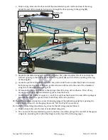
Confirm masking tape is still holding the rudder and the tailwheel in a straight-ahead position.
Being careful to shrink evenly but not burn the heat-shrink tubing, apply heat from an electric
soldering iron for a few seconds along the entire length of the heat-shrink tubing. Remove the
masking tape from the rudder and tailwheel.
27.
Use masking tape to hold the elevators in a level position (even with the horizontal tailplane).
28.
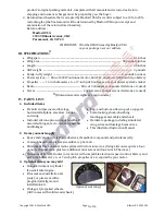
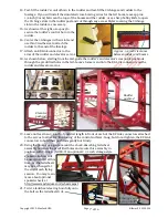
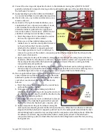
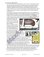
Use the supplied short piece of piano wire that has both an offset-bend and a ‘Z-bend,’ some CA
adhesive and heat-shrink tubing to attach the composite elevator pushrod to the elevator’s
control horn as shown and detailed below:
a.
Twist the piano wire’s Z-bend into the elevator’s
control horn.
b.
Slide a piece of heat-shrink tubing onto the
elevator’s composite control rod; push it forward,
in front of where the metal rod with the offset-
bend and ‘Z-bend’ will be attached to the tail-
wheel’s composite pushrod.
c.
Use a high-speed motor tool’s cutoff wheel
to remove the portion of the elevator servo’s
composite pushrod that extends behind the bend
in the metal elevator pushrod.
d.
Apply and spread a drop of CA adhesive along the outer surface of the metal pushrod extend-
ing forward where it aligns with the composite elevator pushrod. While the CA adhesive is still
wet, hold the elevator’s composite pushrod next to the metal pushrod and slide the heat-shrink
tubing back toward the tail, covering both pushrods.
e.
Confirm masking tape is still holding the elevators in a level position (aligned with the horizon-
tal tailplane). Being careful to shrink evenly but not burn the heat-shrink tubing, apply heat
from an electric soldering iron for a few seconds along the entire length of the tubing.
f.
Remove the masking tape from the elevators and horizontal tailplane.
B. AILERONS, WING WIRES, MAIN LANDING GEAR & ELECTRIC POWER SYSTEM:
Although having ailerons on a Blériot XI is not true-to-scale, being able to use ailerons makes
positive control much easier for most pilots. Follow all the steps in this section if you opt to install
the included ailerons for enhanced flight performance and safety. If you are an advanced scale
pilot who values appearance and you are comfortable making slow turns with rudder, elevator
and throttle only, you may fix the ailerons and aileron hatch covers to the wing with transparent
tape, then mount the wing panels, wing wire supports and wing wires to the fuselage as explained
begininning at step 16 on the next page.
1.
Use your radio or a servo tester to center your aileron servos. (You may learn about servo testers
at
http://www.maxfordusa.com/servo.aspx
.)
2.
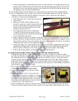
Test-fit your aileron servos to the servo hatch
covers.
3.
Prepare each hatch cover’s servo mount to fit
your servos by using epoxy to attach two wooden
servo pedestals to each servo hatch cover as
shown at the right. When the epoxy is cured, use
the hardware provided with your servos to attach
an aileron servo to each hatch cover.
4.
Select and install servo arms for your aileron servos that are long enough that servo arm travel
will not be limited and attach an EZ Link connector to the outer hole on each aileron servo’s arm.
9
of 16


