background image

Page 

10

 of 18


Copyright 2015    –    PT17 / S150209


60.


Hold your elevator at neutral (on the same level as the horizontal stabilizer) and tighten the EZ Link connector onto the 
elevator pushrod. 

61.


If necessary, cut off the portion of the elevator 
pushrod that extends excessively behind the 
elevator servo‟s EZ Link connector.   
(NOTE: Leave approx. 

1/2

-inch of   

extra pushrod for possible adjustments). 

62.


If you use a glow engine, install your throttle 
servo and connect the throttle pushrod between 
your engine and throttle servo. 
(NOTE: For better appearance and 
airframe longevity, we recommend 
using an electric power system for 
this model. For scale-like flying 
using our U638109 motor, 100A 
ESC and a 19x6 propeller, you 
may use two 4S/4,000 mAh or 
above LiPo batteries in series. For 
extra power, we recommend using 
a 10S or 12S/3,900mAh or above 
LiPo battery – or three 4S LiPo 
batteries in series, with an 18x8 to 
20x8 propeller.) 

63.


If you use an electric motor,   
confirm or correct its direction   
of rotation. 
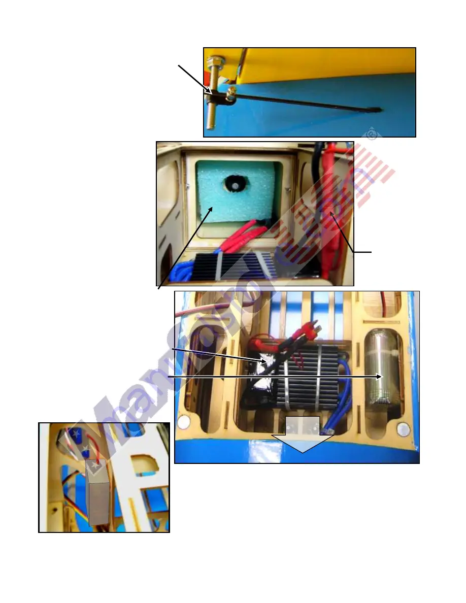
(NOTE: If you are using an electric 
power system, inserting some foam   
rubber (not included) inside the engine 
mounting box may serve as a „safety 
cushion‟ for your flight battery.   
The PT-17‟s spacious cockpit permits 
great flexibility in where you install your 
radio and power system components.   
During all of our EP flight tests the ESC 
was mounted behind and below the 
engine mounting box and we secured   
our radio‟s battery above and to the left 
of the ESC as pictured at the right. Our 
receiver was held in position with 
double-sided foam tape at the right-hand 
side of the servo tray as shown below. 


Wait until you are ready to adjust your PT-17‟s center of gravity to decide on the final positions of your batteries. 
 

IMPORTANT: 

To avoid 

sparks, 

always 

c

onnect the 

ESC to your 

flight battery 

first,   

THEN 

connect the 

anti-spark 
connector.


Nose 

Summary of Contents for 1/5 PT-17 STEARMAN ARF

Page 1: ...is owned by John Mohr who very kindly sent us many detailed pictures of his personal aircraft We also acknowledge and thank Jay Smith editor or Model Aviation for his help and advice on this project...

Page 2: ...smoothly 6 Recheck the operation of this model airplane before every flight to ensure that all equipment is still operating correctly and that the model has remained structurally sound Also before ev...

Page 3: ...ford USA guarantees this kit to be free from defects in material and workmanship at the time of purchase All of our products have been inspected in our factory and are checked again when shipped from...

Page 4: ...ontroller Propeller Not included 18 to 20 inch as recommended for your power system Radio system Not included Minimum of 4 channels and 5 standard servos a 6th servo is needed to control the throttle...

Page 5: ...are using a glow engine point the engine s cylinder head toward the ground Use the L and R on the sides of the engine mounting box as viewed from the pilot s seat to determine which way is down 2 If y...

Page 6: ...d spaced equally behind the nose ring When the glue is fully cured secure the dummy engine to the nose by driving 3 wood screws through the dummy engine s mounting ring through the nose ring and into...

Page 7: ...wn above 24 Remove the tail wheel from the tailwheel strut 25 Attach an 18 inch servo extension to your tailwheel servo NOTE Depending on the length of your servo s lead and where you position your re...

Page 8: ...one cable to each end of the rudder s pull pull control arm 40 Guide the free ends of these cables through the opening on the right side of the tail and forward all the way into the cockpit area 41 P...

Page 9: ...A hinges and to ensure enough space between each half of the elevator and the horizontal stabilizer so the elevator can move up and down freely at least 2 inches 5 cm from level with the horizontal st...

Page 10: ...3 900mAh or above LiPo battery or three 4S LiPo batteries in series with an 18x8 to 20x8 propeller 63 If you use an electric motor confirm or correct its direction of rotation NOTE If you are using an...

Page 11: ...es 38mm Ensure the inner ends of the ailerons do not bind against the cutouts in their adjoining wing panels 66 Apply thin CA to permanently secure each aileron hinge to its wing panel and aileron Rem...

Page 12: ...s of a 12 inch Y harness out through the openings on each side of the fuselage as shown at the right Connect its servo like connector to your receiver s aileron port NOTE If necessary attach a servo e...

Page 13: ...he top and 1 wing wire anchor at the bottom of each strut 91 Guide the wing struts into their openings in the bottom of both left and right panels of the top wing Use epoxy to secure both wing struts...

Page 14: ...chor point near the leading edge of the left side s lower wing panel 1 in the diagram below Bring the wire back into and through the crimp tube then firmly crimp the tube onto the wire as pictured at...

Page 15: ...each half of the horizontal stabilizer at approx 9 inches from the fuselage 106 Tie one end of the supplied black string to either side of the anchor point 107 As pictured below guide the free end of...

Page 16: ...vailable at http www maxfordusa com flyboypilot 2 1 aspx in their cockpits 116 Balance and install the propeller on your motor or engine 117 To ensure the wings struts and wing wires remain secure dur...

Page 17: ...ould deflect to the left as viewed from the rear of the fuselage Review your radio s instruction manual if you require assistance with any radio related or servo adjustment questions 4 If you are usin...

Page 18: ...secure 3 Double check for correct control directions and smooth operation of the throttle ailerons elevator and rudder 4 Get into the habit of moving your transmitter s throttle to minimum before turn...

Reviews: