2-5
FEATURES
www.maxcessintl.com
Fife GMA-BL
MI 2-264 1 B
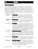
Status bar definitions
The status bar located horizontally across the top of the Operator Level screen remains
visible at all times. The number on the left side of the status bar contains the numerical
address of the connected motor controller and it should always be 1. The number on the
right side of the status bar indicates a hierarchical screen number. The first numerical value
indicates the operation mode (1=Manual, 2=Servo-Center, 3=Automatic). The second
alphabetic character indicates the sensor mode (A=S1, B=S2, C=S1-S2). This screen number
uniquely identifies each screen of the operator interface. The status bar also displays various
icons which are described below.
OPERATION MODE One of these icons will appear to indicate the
operation mode of the GMA-BL Actuator Controller. These do not
appear on the Operator Level screen since the mode buttons already
indicate this information. These will only appear while in the setup
screens.
SENSOR SELECTION One of these icons will appear to indicate the
currently selected sensor mode. These do not appear on the Operator
Level screen since the SENSOR button already contains this
information.
MENU TIMEOUT The menu screens in the operator interface close
automatically after 3 minutes of touch screen inactivity. The inactivity
timeout option and the timeout value are configurable. The clock
icons will appear during stages of the timeout process as the inactivity
timer counts down. If a timeout occurs, the respective menu will abort
any changes applied and return to the Operator Level screen. Some
service-related screens are immune from the timeout option and are
indicated by the presence of the orange clock icon.
LOGIN AUTHORIZATION LEVEL When security has been configured,
one of these icons will appear to indicate the authorization level of the
current user. Level 1 has the least access while level 3 has the most.
Security is disabled in the factory default configuration so these icons
will not be displayed. All menu screens are accessible when security is
disabled.
READ ONLY MENU When security is enabled, options are available to
make menus “read only”, allowing an operator to view the settings but
not change them. This icon will appear when the active menu is a
“read only” menu.
DIGITAL INPUT COMMAND This icon appears when a valid digital
input command is present. Depending on the command, some touch
panel controls may be disabled during this time. A red arrow in the
down direction indicates digital input influence is disabled. A red up
arrow indicates the digital outputs are disabled.
Summary of Contents for Fife GMA-BL
Page 1: ...Fife GMA BL Actuator Controller Quick Start Manual EN MI 2 264 1 B...
Page 2: ......
Page 15: ......


