


N
‐
i
‐
HP
Inverter
air
/
water
heat
pump
chillers
with
axial
fans
7
5
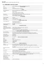
TECHNICAL
CHARACTERISTICS
The
N
‐
i
‐
HP
water
chillers
and
heat
pumps
series
are
designed
for
applications
in
residential
and
industrial
areas,
these
units
are
extremely
versatile
and
can
operate
in
heat
pump
mode
with
the
ability
of
hot
water
generation
at
a
temperature
of
55°C
for
environmental
heating
and
sanitary
applications.
The
DC
Brushless
Inverter
compressor
technology,
matched
with
the
electronic
expansion
valve,
the
pump
and
the
variable
speed
blower
are
generally
used
for
optimizing
the
power
consumption
and
efficient
operation
of
the
refrigerating
components.
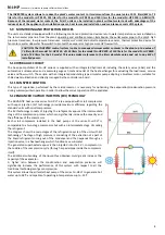
5.1
FRAME
All
N
‐
i
‐
HP
units
are
made
up
of
hot
‐
galvanised
thick
sheet
metal,
painted
with
polyurethane
powder
enamels
at
180°C
to
ensure
the
best
resistance
against
atmospheric
agents.
The
front
panel
is
hinged
to
the
lift
side
to
allow
access
to
the
internal
components
for
inspection
and
maintenance.
The
screws
and
the
inserts
are
made
up
of
galvanized
steel.
5.2
REFRIGERANT
CIRCUIT
The
refrigerant
circuit
has
been
manufactured
according
to
the
UNI
EN
13134
directive
concerning
welding
procedures.
The
refrigerant
gas
employed
in
these
units
is
R410A
type.
The
refrigerant
circuit
includes
in
its
basic
version:
4
‐
way
reversing
cycle
valve,
electronic
expansion
valve,
liquid
separator,
liquid
receiver,
check
and
maintenance
valves,
pressure
safety
device
according
to
PED
regulation
(high
pressure
switch),
pressure
transducers
to
accurately
adjust
the
evaporating
and
condensing
pressures,
filters
for
expansion
valve
to
prevent
its
clogging.
The
versions
with
vapour
injection
also
include
heat
exchanger
to
produce
vapour,
electronic
injector
valve,
the
ON
‐
OFF
valves
of
injection
in
case
of
two
compressors.
5.3
COMPRESSORS
The
compressors
are
scroll
type
DC
inverter
designed
for
use
with
R410A
refrigerant,
and
are
mounted
on
a
rubber
material
acting
as
a
shock
absorber.
The
compressors
of
the
injection
versions
are
designed
to
optimize
the
efficiency
of
the
refrigerant
cycle
under
low
ambient
temperatures
conditions
and
are
supplied
with
connection
for
vapour
injection.
The
crankcase
heater
operates
when
the
compressor
remains
off
for
at
least
30
minutes
and
if
the
discharge
temperature
is
below
20°C
(with
hysteresis
of
2.0°C).
When
the
compressor
restarts,
the
crankcase
heater
will
stop
operation.
We
recommend
to
turn
on
the
unit
and
to
put
it
in
standby
mode
at
least
6
hours
before
the
first
startup.
The
checking
of
the
compressors
is
possible
through
the
front
panel
of
the
unit
that
allows
the
maintenance
of
the
compressors
even
if
the
unit
is
in
operation.
5.4
AIR
‐
SIDE
EXCHANGERS
The
air
‐
side
heat
exchanger
is
made
up
of
copper
pipes
and
aluminium
fins.
The
copper
pipes
diameter
is
7,94
mm,
the
thickness
of
the
aluminium
fins
is
0,12
mm.
The
pipes
are
mechanically
expanded
into
the
aluminium
fins
in
order
to
improve
the
heat
transfer
coefficient.
The
geometry
of
these
heat
exchangers
ensures
a
low
value
air
‐
side
pressure
drop
and
then
it
allows
the
use
of
fans
with
low
number
of
revolutions
(with
the
advantage
of
reducing
the
unit
noise
level).
5.5
FAN
MOTOR
The
fan
motor
is
axial
type
with
plastic
aerofoil
blades.
They
are
statically
and
dynamically
balanced
and
supplied
with
a
safety
fan
guard.
The
fan
motor
is
a
modulated
brushless
type,
directly
coupled
and
equipped
with
an
integrated
thermal
overload
protection.
The
protection
class
of
the
motor
is
IPX4
according
to
CEI
EN
60529.
5.6
USER
‐
SIDE
HEAT
EXCHANGERS
The
user
‐
side
heat
exchanger
are
made
up
of
AISI
316
stainless
steel
braze
‐
welded
plates
type,
and
are
factory
insulated
with
flexible
close
cell
material
and
are
equipped
with
an
antifreeze
electric
heater
(optional
accessory:
KA).
Each
evaporator
is
equipped
with
a
temperature
sensor
for
antifreeze
protection
that
activates
the
circulator,
even
in
the
case
where
the
unit
is
turned
off
when
meeting
the
setting
parameters
by
controller.
5.7
ELECTRICAL
CONTROL
PANEL
BOARD
The
electrical
control
panel
board
is
manufactured
according
to
European
Union
directives
currently
in
force.
To
access
to
the
electrical
control
panel
board,
you
must
open
the
front
panel,
lock
the
disconnect
switch
in
the
Off
position,
(presence
of
a
door
lock
system)
and
by
mean
of
a
flat
‐
head
screwdriver,
turn
to
open
quarter
‐
turn
the
two
locks.
The
protection
degree
is
IP34.
The
electric
box
is
supplied
with
a
terminal
block
completed
with
free
contacts
for
remote
ON
‐
OFF,
winter/summer
change
over,
auxiliary
heater,
sanitary
water
temperature
sensor,
management
of
external
3
‐
way
valve
and
contacts
for
remote
control
panel.
The
addition
of
the
optional
module
GI
enables
the
management
of
further
functions
of
the
plant.
5.8
CONTROL
SYSTEM
The
N
‐
i
‐
HP
units
are
equipped
with
a
microprocessor
adopting
an
overheating
control
logic
program
through
the
thermostatic
valve
driven
by
the
pressure
transducers
signals.
The
CPU
also
manages
the
following
functions:
water
temperature
regulation,
antifreeze
protection,
compressors’
time
setting,
alarm
reset,
alarms
management
and
operation
LED.
Upon
request,
the
microprocessor
can
be
connected
to
a
BMS
remote
control
system
and
to
the
simpler
HNS
system
with
our
terminal
units.
The
control
system
together
with
the
INVERTER
technology
and
the
on
board
sensors
can
continuously
monitor
and
adapt
the
performance
of
the
inverter
compressor,
of
the
circulator
pump
and
of
the
fan
motor.


