


ADVANTIX
SPA
Via
Mansoldo
Gettuglio
–
Loc.
La
Macia
Z.A.I
–
37040
ARCOLE
(Verona)
20
OPERATING
LIMITS
20.1
EVAPORATOR
WATER
FLOW
RATE
The
nominal
water
flow
rate
is
referred
to
a
∆
T
equal
to
5°C,
between
the
evaporator’s
inlet
and
outlet
temperatures.
The
allowed
maximum
flow
rate
is
corresponding
to
∆
T=3°C.
Higher
values
may
produce
too
high
pressure
drops.
The
allowed
minimum
water
flow
rate
is
corresponding
to
∆
T=8°C.
Insufficient
values
may
produce
too
low
evaporating
temperatures
with
the
intervention
of
safety
devices
which
would
stop
the
unit
and,
in
some
particular
cases,
the
water
can
freeze
in
the
evaporator
coil
which
can
breakdown
the
refrigeration
circuit.
We
enclosed
below
a
most
accurate
table
showing
the
minimum
flow
rates
that
to
ensure
for
the
plate
heat
exchanger
for
a
the
proper
operation
of
unit
according
to
the
model
(
note:
the
water
flow
switch
is
used
for
preventing
the
freezing
sensor
from
failure
in
the
case
of
insufficient
water
flow
but
it
does
not
ensure
the
minimum
flow
rate
required
in
order
the
unit
can
work
properly)
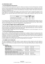
Models
N
‐
i
‐
HP
0125
0235
0250
Cooling
capacity
for
reference
[kW]
27,5
38,4
48,7
Minimum
water
flow
rate
that
to
ensure
[L/s]
0,82
1,15
1,45
As
a
first
approch,
and
in
the
absence
of
other
detection
systems,
the
proper
flow
rate
for
getting
the
best
performance
from
your
unit
can
be
found
at
maximum
speed
of
the
circulator,
using
the
pressure
gauges
for
controlling
the
pressure
difference
between
the
return
and
the
delivery
water
on
the
outside
water
connections
of
the
unit
and
make
sure
that
such
value
is
equal
or
less
than
the
static
pressure
indicated
on
the
curves
shown
in
paragraph
15
for
the
respectives
models.
20.2
COLD
WATER
TEMPERATURE
(SUMMER
OPERATION)
The
allowed
minimum
temperature
at
the
evaporator’s
outlet
is
5°C;
for
more
lower
temperatures
please
contact
us.
In
this
case
contact
our
company
for
the
feasibility
study
and
evaluation
of
changes
to
be
made
according
to
your
requests.
The
maximum
temperature
that
can
be
maintained
at
the
outlet
of
the
evaporator
is
25°C.
Higher
temperatures
(up
to
a
maximum
of
40°C)
can
anyway
be
tolerated
during
transitions
and
start
‐
up
phases
of
the
system.
In
all
cases,
the
maximum
electrical
input
occurs
for
the
heat
pump
operating
mode
at
a
water
outlet
temperature
of
55°C
and
with
outdoor
temperature
of
‐
10°C.
20.3
HOT
WATER
TEMPERATURE
(WINTER
OPERATION)
Once
the
system
is
working
at
the
right
temperature,
the
inlet
hot
water
temperature
should
not
to
be
lower
than
25°C;
the
lowest
values
that
are
not
related
to
transitional
or
start
‐
up
stages
may
cause
system’s
malfunction
and
possible
compressor
breakdowns.
The
maximum
outlet
water
temperature
have
not
to
exceed
55°C.
At
this
temperature,
the
power
consumption
and
performance
in
terms
of
C.O.P.
are
enhanced
if
the
outdoor
temperature
is
higher
than
5°C,
even
if
the
unit
is
still
able
to
work
up
to
the
limit
of
‐
15°C
(
‐
25°C
for
versions
with
injection).
For
higher
temperatures
than
those
pointed
out,
especially
if
have
a
concomitant
with
the
reduction
of
the
water
flow
rate,
it
may
cause
abnormalities
to
the
normal
operating
of
the
unit,
or
the
safety
devices
act
in
critical
cases.
20.4
AMBIENT
AIR
TEMPERATURE
The
units
are
designed
and
manufactured
to
operate,
in
summer
operation,
with
the
condensate
control,
with
outdoor
air
temperatures
ranging
between
‐
10°C
and
46°C.
While
operating
as
a
heat
pump,
the
allowed
range
of
the
outdoor
temperature
goes
from
‐
15°C
(
‐
25°C
for
versions
with
injection)
to
40°C
as
a
function
of
the
water
outlet
temperature
as
indicated
in
the
below
table.
Operation
limits
Water
chiller
mode
Ambient
temperature
Min.
‐
10°C
Max.
+46°C
Water
outlet
temperature
Min.
+5°C
Max.
+25°C
Heat
pump
mode
Ambient
temperature
(versions
of
standard/injection)
Min.
‐
15°C
Max.
+30°C
Water
outelt
temperature
(versions
of
standard/injection)
Min.
+25°C
Max.
+55°C/58°C
Heat
pump
mode
for
sanitary
hot
water
Ambient
temperature
with
maximum
water
temperature
48°C
Min.
‐
15°C
Max.
+40°C
Ambient
temperature
with
maximum
water
temperature
55°C
Min.
‐
15°C
Max.
+35°C
Water
outelt
temperature
(versions
of
standard/injection)
Min.
+20°C
Max.
+55°C/58°C


