Max-Thrust Douglas A1 Skyraider Assembly And Instruction Manual Download Page 5

1.   Hinge check

Check that all control surface hinges are firmly secured.  If required they can be glued in 
position using a small quantity of the supplied adhesive.

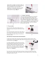
2.   Horizontal Tail Plane

Fix the elevator control horn in the moulded recess 
as shown using two M2 x 15mm screws, (

image 1

). 

Make certain that the plastic horn is fitted to the 
correct side, with the plastic reinforcement plate 
fixed in the moulded recess on the top side of the 
elevator. 


1

Using a light grade abrasive paper, lightly abrade the painted mating surfaces where the 
horizontal tail plane joins the fuselage. This provides a good key for the adhesive. (

image 2

). 

Glue the horizontal tail plane in position using the supplied adhesive, (

image 3

). Secure in 

position using the two M3 x 40mm screws, (

image 4

). Use the adhesive sparingly towards 

the edges of the parts to be glued and immediately wipe any excess from the joint.


2


4

3. Vertical Fin & Rudder

Fix the plastic rudder control horn in the moulded recess using two M2 x 30mm screws, 
(

image 5

).  Make certain that the plastic horn is fitted to the correct side, with the 

reinforcement plate fixed in position on the opposite side of the rudder.

Using a light grade abrasive paper, lightly abrade the painted mating surfaces of the rudder 
and horizontal tail plane to provide a good key for the adhesive, (

image 6). 


5

  6

4

3

Summary of Contents for Douglas A1 Skyraider

Page 1: ...model is not a toy It requires skill to fly and is not recommended for the novice pilot It should not be operated by children without the supervision of a suitably experienced adult Max Thrust reserve...

Page 2: ...or assembling and setting up of this model Failure to do so could result in a loss of control and possibly a crash Overview Thank you for purchasing this MAX THRUST Douglas A1 Skyraider radio controll...

Page 3: ...rop Tank 2 Wing Panels 10 Bombs 3 Horizontal Stabilizer 11 Retracts and Doors 4 Fin Rudder 12 Fixings Pack 5 Aerial 13 Propeller 6 Wing Guns 14 Propeller Adaptor 7 Canopy 15 Y Leads 8 Main Spar 2 1 2...

Page 4: ...m Servo Tester Power Tech Part No PT ACC ST Please 0ote EPOFLEXY is a very tough and durable material perfect for the manufacture of model aircraft When using screwed fixings with EPOFLEXY components...

Page 5: ...ns the fuselage This provides a good key for the adhesive image 2 Glue the horizontal tail plane in position using the supplied adhesive image 3 Secure in position using the two M3 x 40mm screws image...

Page 6: ...lowering process The wheels should be located on the outside edge of the oleos when the retracts are lowered This can be tested with the units powered up or with a Power Tech Servo Tester 9 THE RETRA...

Page 7: ...are routed correctly and there are no gaps at the root of the panels image 12 12 0ote Due to the moulding process a very small amount of trimming may be required to obtain a perfect fit For ease of tr...

Page 8: ...le check that all plugs are connected to the correct outputs on your receiver and that all leads are routed in a neat and tidy manner Mount the receiver inside the fuselage as shown image 16 using you...

Page 9: ...fixing to provide adequate security Because most experienced pilots will have a preferred method of battery retention this has not been included with the model We recommend the use of additional strap...

Reviews: