background image

11 

PROPELLER DISASSEMBLY

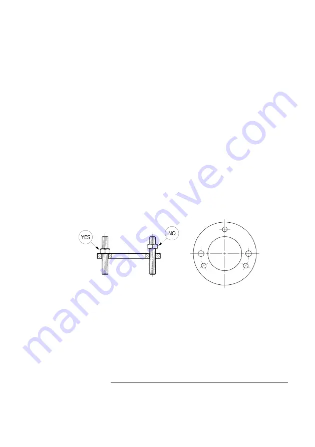
In order to remove the propeller you must first remove the zinc and the nut-locking 
screws; then fasten a perforated washer, supplied only on request, on the zinc-holding 
ring by means of five threaded grub screws (fig. 8). Screw the five threaded grub screws 
(long enough and provided with five nuts) into the five threaded holes obtained in the 
zinc-holding ring, making sure that all five threaded grub screws are tightened to the 
bottom of their own threaded hole. Then lean all five nuts on the perforated disc which 
acts as extractor (see fig. 8). Start unscrewing very smoothly the propeller-locking nut, 
which will press against the washer (fig. 8) and check that all five extraction screws 
work together with the same load to extract the propeller. Slowly unscrew the nut 
and be careful not to overload the screws to prevent them from breaking. When, due 
to nut unscrewing, stress is applied to all 5 screws, it may be helpful to knock lightly 
on the propeller body with a plastic mallet. Said knocks will detach the propeller hub 
from the propeller shaft.

Fig. 8

Spare parts reference code

Summary of Contents for WHISPER 5 BLADES

Page 1: ...installation instructions MAX PROP WHISPER patented propeller...

Page 2: ...AX PROP WHISPER parts are not interchangeable If you receive more than one propeller at the same time for example if two propellers have to be installed on a boat and for any reason the received prope...

Page 3: ...ly in line with the axis of the propeller body making sure that their profile is as shown in fig 2 e Before launching the boat it is absolutely necessary to operate as follows Lock the propeller shaft...

Page 4: ...70 26 275 320 370 415 460 505 550 590 645 690 735 28 300 350 400 450 500 550 600 650 700 750 800 30 325 380 435 490 545 600 655 705 760 815 870 Fig 3 Fig 3 PITCH ADJUSTMENT The pitch of MAX PROP WHISP...

Page 5: ...ith a threaded grub screw and precisely defining the value of the rotation angle of the screw rod when switching from fastening in a groove to fastening in the next groove All the propellers have been...

Page 6: ...tment position thereof If the user wants to know the value of the pitch set on his propeller he should remember that the number stamped on the screw rod see fig 5 refers to the propeller pitch in degr...

Page 7: ...W ROD RANGE OF REGULATION PITCH IN DEGREES 24 24 22 22 20 20 18 18 16 16 MIXED PROCEDURE A B OPTIONAL SUPPLY CUSTOMER CAN ASK THE SCREWS HE PREFERS ONLY TWO SCREWS ARE FREE OF CHARGE PROCEDURE B OPTIO...

Page 8: ...to the next one i e by only one hole the propeller pitch will vary by one degree The adjustment range is standard that is maximum pitch 24 degrees for the forward motion and minimum pitch 16 degrees f...

Page 9: ...ving on one tooth of the hub aft side and two teeth of the zinc holding ring are marked with L left and R Right respectively If you reassemble the zinc holding ring placing the tooth R at the tooth of...

Page 10: ...and will not feather You can actually use this method to rotate the shaft when the latter is connected to a generator IMPORTANT WARNINGS Carefully follow the following instructions Before reversing m...

Page 11: ...bottom of their own threaded hole Then lean all five nuts on the perforated disc which acts as extractor see fig 8 Start unscrewing very smoothly the propeller locking nut which will press against the...

Page 12: ...the jurisdiction of the Milan Courts Italy 9 The transport cost charged in the invoice from Max Prop doesn t include any insurance The costumer notes that the insurance even if pre paid from Max Prop...

Reviews: