20
Secondary of the transformer: Use the table below
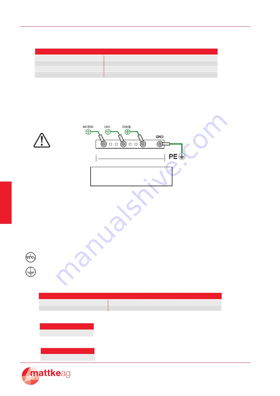
3.1 Connections to earth and ground
Make sure that the servodrive and the motor are connected to earth in accordance with the
current norms. This connection must be done by using a copper bar, mounted on insulating
supports:
Then follow these indications:
1. Connect to the ground bar:
the GND pin 3 of the Dc One
the internal „0V“ zero voltage of the CNC;
the earth terminals of the PLC/CNC frames;
the „0V“ of the auxiliary supply;
2. Connect the ground bar to the zinced panel of the drive by using a screw, then connect
that screw to earth.
3. Connect earth to the motor’s
It suggests a conductive connection as much as possible to the chassis, or the heatsink,
or the mounting panel of the electrical box.
It refers to the earth connection.
Motor and Power cable (as norm EN60204)
Control signals cable (as norm EN60204)
Feedback signals cable (as norm EN60204)
Ground bar
Earth point connection
L bar
Bar's section
0,5 .. 1m
30 x 5 mm
1..2m
40 x 5 mm
Make sure that the servodrive and the motor are connected to earth in accordance with the current
norms. This connection must be done by using a copper bar, mounted on insulating supports:
L bar
then follow these indications:
1. Connect to the ground bar:
the GND pin 3 of the Dc One
the internal "0V" zero voltage of the CNC;
the earth terminals of the PLC/CNC frames;
the "0V" of the auxiliary supply;
2. Connect the ground bar to the zinced panel of the drive by using a screw, then connect that screw
to earth.
3. Connect earth to the motor’s
It suggests a conductive connection as much as possible to the chassis, or the heatsink,
or the mounting panel of the electrical box.
It refers to the earth connection.
SECTION
SIZE (A)
1,5mm
2
/ 15AWG
2/4 4/8 7/14
2,5mm
2
/ 13-14AWG
10/20
SECTION
0,5mm
2
/ 20AWG
SECTION
0,25 - 0,35mm
2
/ 22 -24AWG
FUSE F2 (A) SIZE Drive (A)
5
8
12
16
2/4
4/8
7/14
10/20
SECTION SIZE (A)
1,5mm2 / 15AWG
2/4 4/8 7/14
2,5mm2 / 13-14AWG
10/20
SECTION
0,5mm2 / 20AWG
SECTION
0,25 - 0,35mm2 / 22 -24AWG
Summary of Contents for MDCA 100
Page 1: ...1 MDCA XXX XX Precision Servodrive for DC motors...
Page 2: ...2...
Page 4: ...4 MDCA XXX XX...
Page 36: ...36 V 1 0...


