background image

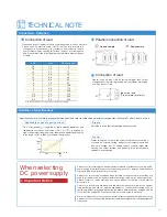
TECHNICAL NOTE

AWG

Max current(A)

mm

2

18
16
14
12
10

8
6
4
2
1

1/0
2/0
3/0

1.1
1.3
2.1
3.3
5.3
8.4
13
21
33
42
53
67
85

2
7

11
18
23
39
67

106
170
209
270
330
350

Connection of load

P.S

Parallel connection of load

P.S

Di

Connection of load

Ripple

Preset

Io

Vo

100%

0

10%

10%

100%

F.S

F.S

*

When selecting 

DC power supply

Products on this catalog have been manufactured with consideration of safety as DC 
power supply, however please follow instruction manual for operation and make sure 
to ground the ground terminal for your safety.

Products on this catalog have been manufactured on the precondition that they are 
used in ground electric potential or within the range of the above series operation. 
Please contact our sales staff when using the product for floating of high electric 
potential, etc.

Products on this catalog are manufactured with consideration for protection against 
load discharge. However for specific experiment or continuous discharge such as 
sputtering, product may need discharge resistance between power supply and load 
or could not be used at all. Please consult with our sales staff in advance.

We recommend that you contact our sales staff with your requirement before choosing 
a product so that you can get the best product and the safety as high-voltage equipment 
is assured.

Important Notice

"F.S × catalog value(

*

)" is applied for ripple, stability, regulations and 

temperature coefficient, and "value if F.S × ±1%(

*

)" is applied for 

high-voltage output linearity, monitor linearity and display linearity, both 
in the range of 10% to 100% of maximum rating output.

Definition of specifications

Connection · Operation

Applicable scope of specifications

· Please use a short lead wire that is sufficiently thick for the connection.
·  Please use PVC electric cable (105°C) that can fully tolerate the 

voltage used. It is necessary to consider current capacity, length 
limit of output wire by sensing (0.5V/lead) and so on for wiring with 
load. Please refer to the following diagram to determine the thickness 
of cable.

Please insert a diode of which rating is bigger than output 
voltage and current of power supply to protect the power supply 
from kick back of load.

Specifications in this catalog, except otherwise specified, refer to values when maximum rating output (full scale

*

) after 2-hour warm up.

Use several cables or copper bar for model over 350A.

Load 1

Load 2

Load 3

P.S

Load 1

Load 2

Load 3

Bad example

Good example

Inductive load
(Transformer or motor)

Indication is in rms that includes high-frequency noise.

Preset value does not show the actual output status accurately. If 
you need an accurate setting, conduct actual output without load 
and set a voltage. Also for setting current, conduct output after 
shorting the output terminal and gradually raise current before 
setting at a desired value. 

11

Summary of Contents for REK Series

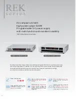
Page 1: ...nt Power Supply REK Series www matsusada com High power Versatile Programmable DC power supply Compact High power of 5 5kW except some models REK series NEW NEW except some models 6V to 650V 2 5A to 600A 1 6kW to 5 5kW ...

Page 2: ...cise monitoring with better recognition Operability and safety are improved with new features of key lock function and acceleration rotary encoder which accelerate the output ramp up with the speed of rotating the encoder 7kW 10kW models are also available 1 6kW to 2 5kW models 3 6kW to 5 5kW models Featuring broad output range and low noise switching configuration REK series is an ideal power sup...

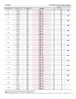
Page 3: ... to 25 0 to 36 0 to 55 0 to 10 0 to 16 6 0 to 24 0 to 36 0 to 8 0 to 12 5 0 to 18 0 to 27 0 to 5 3 0 to 8 3 0 to 12 0 to 18 0 to 3 2 0 to 5 0 to 7 0 to 11 0 to 2 7 0 to 4 1 0 to 6 0 to 9 0 to 2 5 0 to 3 8 0 to 5 5 0 to 8 5 10 10 10 10 10 10 10 10 10 10 10 15 10 12 15 15 20 20 20 20 20 20 30 30 20 30 30 30 20 18 30 30 20 20 30 30 20 25 30 30 30 25 30 30 40 40 40 40 50 50 50 50 100 100 100 100 150 1...

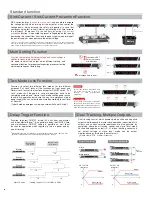
Page 4: ...output when different setting and convenient function for production inspection process or testing which require frequent data taking Memory a Memory b Memory c 3 Set voltage and current 1 2 Press down SET Select a memory with 3 buttons NOTE It is not possible to stabilize the output by controlling back current In case of load which has inverse voltage or over rated voltage such as inductive load ...

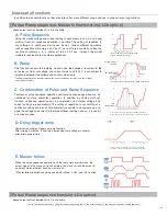
Page 5: ...h range 1 0s to 99 9h respectively tb tc toff a b c ta t1 Note The operation accuracy of the timer when sequensing is 0 5 Be careful when you use it by the long term running operation t2 Output ON Output OFF t1 a c b ta t2 tb t3 tc t4 toff t1 and t2 can be set with range 0 to 999s respectively t1 t2 t3 and t4 can be set with range 0 to 999s respectively ta tb tc and toff can be set with range 0 0s...

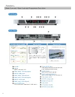
Page 6: ...ogramming display Light on when voltage current remote control Output preset switch OVP OCP setting switch Keylock setting switch Exhaust hole AC input terminal M4 Not Sink Current switch 1 10 11 12 13 14 15 16 17 18 2 3 4 5 6 7 8 9 Front Panel Rear Panel nt Panel 1 1 2 3 6 5 8 9 1 0 11 12 13 14 15 4 7 Voltage Control 0 to approx 10k Current Control Blackout Protection Io Load VL Vo R S S OUTPUT 0...

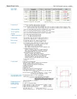
Page 7: ...n Interlock Other functions Transient response time Operation temperature Storage temperature Storage humidity Dielectric voltage Accessories 50 Temp C Input Voltage V Input Voltage V Output Power kW 40 85 100 120 200 240 264 1 6 1 2 85 100 120 200 240 264 Keylock to avoid misoperation Digital master slave operation up to 250V for series operation Max 32 units for parallel or series connection Com...

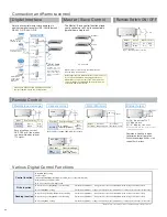
Page 8: ... V COM ON when OUTPUT ON when each mode FLT OUTPUT CV CC TB1 ON when fault CV CC Delay trigger function at Master Slave control can be set for each unit Furthermore delay trigger function at Master Slave control can cancel one control functions except for Output by switching Remote Local and can set voltage and current preset Possible to change 10k to 0 for fail safe A A A RS 232C RS 485 GPIB A CO...

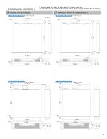
Page 9: ...8 35 0 18 4 5 16 85 428 16 81 427 2 36 60 17 17 436 4 M4 4 M4 3 Ø0 33 8 5 2 M6 1 38 35 0 18 4 5 16 85 428 16 81 427 2 36 60 17 17 436 Weight 8kg typ Weight 8kg typ Weight 14kg typ Weight 14kg typ 1 6kW 2 5kW Models 1 6kW 2 5kW Models 3 6kW 5 5kW Models 3 6kW 5 5kW Models O I 1 97 50 3 76 2 3 47 88 1 18 31 465 19 482 6 8 6x10 There are exhaust holes on rear panel for forced air cooling In case plac...

Page 10: ... 1 CO G32 B 32 units can be connected to 1 CO E32 32 units can be connected to 1 CO U32 In case power supply will be use following condition make sure this options selected Noisy environment such as factories ex usage of motor and coil around load or power supply Usage on high voltage floating more than 250V In case the distance between power supply and controller PC or PLC is longer than 2 meter ...

Page 11: ... is assured Important Notice F S catalog value is applied for ripple stability regulations and temperature coefficient and value if F S 1 is applied for high voltage output linearity monitor linearity and display linearity both in the range of 10 to 100 of maximum rating output Definition of specifications Connection Operation Applicable scope of specifications Please use a short lead wire that is...

Page 12: ...ed to be defective as satisfactory to us we at our sole discretion repair or replace such defective Products at no cost to the purchaser We assume no liability to the purchaser or any third party for special incidental consequential or other damages resulting from a breach of the foregoing warranty This warranty excludes any and all other warranties not set forth herein express or implied includin...

Reviews: