background image

11

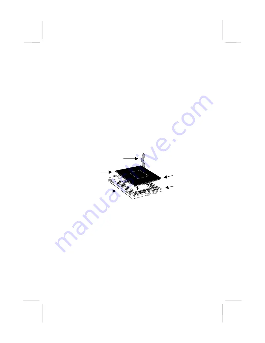
Installing a PPGA Celeron in the Socket-370

This mainboard is installed with a PGA370 ZIF processor socket. This
socket will only support the PPGA Celeron processor. 

Do not try to insert

a socket-7 processor such as a Pentium or Pentium-compatible
processor

. The PPGA Celeron processors all run over a 66 MHz system

bus and have internal clock speeds ranging from 300 to 433 MHz.
Configuration of the processor is made automatically using the
mainboard BIOS (see the Setup chapter).

1.  Locate the zero insertion force (ZIF) PGA370 socket for the

processor.

2.  On the socket and on the processor, identify the pin 1 corner. On the

socket, the pin-1 corner is opposite the hinge of the locking lever,
and it has one hole missing from the corner. On the processor, the
pin-1 corner has a slight bevel.

3.  Push the socket locking lever away from the socket to unhook it.

Swing the lever into the upright position.

4.  Insert the processor into the socket taking care that you have

matched the pin 1 corners. No force is required, and the processor
should seat smoothly into the socket.

5.  Swing the locking lever down and hook it under the latch on the side

of the socket to lock it in place.

6.  Locate the power connector for the processor cooling fan CPU FAN1.

If your processer has a cooling fan installed, connect the cable from
the cooling fan to CPU FAN1.

Pin-1 corner

Pin-1 corner

Locking lever

Celeron processor

Socket-370

Summary of Contents for MS7117C

Page 1: ...e separation between the equipment and the receiver Connect the equipment onto an outlet on a circuit different from that to which the receiver is connected Consult the dealer or an experienced radio...

Page 2: ...fitness for any particular purpose Further the manufacturer reserves the right to revise this publication and to make changes from time to time in the content hereof without obligation of the manufact...

Page 3: ...Option 30 Power Management Setup Option 33 PNP PCI Configuration Option 35 Load BIOS Defaults Option 37 Load Setup Defaults Option 37 Integrated Peripherals Option 37 Supervisor Password and User Pass...

Page 4: ...rts 66 MHz 100MHz or a 133 MHz memory bus so you can use 66MHz or 100MHz memory chips or higher performance PC 133 memory chips The board is installed with an integrated PCI 3D sound system and has a...

Page 5: ...re the mainboard for optimum performance Software Use the Software Chapter to learn how to use the software drivers and support programs that are provided with this mainboard Checklist Compare the con...

Page 6: ...supported processor clock speeds using the BIOS setup utility It is not necessary to set switches or jumpers Choice of Memory Options The board has three DIMM slots for the installation of 168 pin 3 3...

Page 7: ...nects the line and telephone RJII sockets to the board The fax modem supports the V 90 protocol that allows transmissions at up to 56Kbps and is fully compatible with earlier transmission and error co...

Page 8: ...er On Feature Using the system BIOS setup program you can configure the system to turn on using a keyboard typed password or hot key A green keyboard is not required Programmable Firmware The mainboar...

Page 9: ...n t have a wrist strap discharge any static by touching the metal case of a safely grounded device before beginning the installation Leave all components inside their static proof bags until they are...

Page 10: ...s that you intend to install The mainboard has a set of I O ports on the rear edge Ensure that your case has an I O template that supports the I O ports and expansion slots Mainboard Guide Use the fol...

Page 11: ...itches and indicators CPUFAN1 Power connector for CPU cooling fan CASEFAN1 Power connector for case cooling fan WOM1 Connector for modem wake up WOL1 Connector for LAN wake up SPDIF1 SPDIF In out conn...

Page 12: ...2 port for pointing device upper port PS 2 port for keyboard lower port LPT1 External parallel port JS1 Upper External game MIDI port JS1 Lower Audio jacks for left to right line out line in microphon...

Page 13: ...wing steps Install the processor Install the memory module s Check the jumper settings Install the Processor This board has a socket 370 for a PPGA Celeron processor You can install one PPGA Celeron L...

Page 14: ...pin 1 corner On the socket the pin 1 corner is opposite the hinge of the locking lever and it has one hole missing from the corner On the processor the pin 1 corner has a slight bevel 3 Push the sock...

Page 15: ...nd the first memory module should be installed in slot DIMM1 the second in slot DIMM2 and the third in slot DIMM3 If the modules use standard SDRAM the maximum capacity of each module is 128MB if the...

Page 16: ...slot down 4 Install the DIMM module into the slot and press it carefully but firmly down so that it seats correctly The latches at either side of the slot will be levered upwards and latch on to the e...

Page 17: ...mounted on the mainboard Some jumpers might be arranged in a series with each pair of pins numbered differently Jumpers are used to change the electronic circuits on the mainboard When a jumper cap is...

Page 18: ...switch to turn your system on If you enable this property you need to define the password or the hot keys using the setup utility See Chapter 3 for more information Function Jumper Cap Disable keyboar...

Page 19: ...ident Function Jumper Cap Enable flash BIOS Short pins 1 2 Disable flash BIOS Short pins 2 3 JP9 133MHz System Bus Frequency Select Jumper Use this 3 pin jumper to set the system bus frequency In the...

Page 20: ...sion slot blanking plate from the system chassis that is adjacent to the fax modem connector 3 Install the fax modem extension bracket on to the J1 connector as shown below The RJ11 Line and Telephone...

Page 21: ...ly on the device connector If the connector is not keyed make sure that you match the pin 1 side of the cable connector with the pin 1 side of the device connector Each connector has the pin 1 side cl...

Page 22: ...can supply power to the fan from the case fan power connector CASEFAN1 Connect the power cable from the fan to CASEFAN1 3 Locate the bank of switch and indicator connectors PANEL These connectors prov...

Page 23: ...use either the infrared port or the second serial port See Chapter 3 for more information 2 The mainboard has three audio connectors CD1 is a 4 pin audio connector which can be used to input the audio...

Page 24: ...rds install them in on of the four PCI slots If you have 8 16 bit legacy ISA cards you can install them in one of the two ISA slots Note The PCI slot PCI4 and the ISA slot ISA1 are shared slots This m...

Page 25: ...he wake on LAN connector WOL1 If you have installed an internal fax modem expansion card connect it to the wake on modem connector WOM1 2 If you have installed a Sound Blaster PCI audio expansion card...

Page 26: ...is a game MIDI port You can use this port to connect a joystick or a MIDI device to your system 4 The lower part of JS1 is three audio jacks The left side jack is for a stereo line out signal The midd...

Page 27: ...e limited by the kind of hardware you are using for example the rating of your memory chips In certain circumstances the system may generate an error message which asks you to make changes to the setu...

Page 28: ...ny of the other values in the table of items When an item is highlighted you can change the value by pressing the PageUp or PageDown keys or the Plus or Minus keys The PageUp and Plus keys cycle forwa...

Page 29: ...ey held when the setup utility was started You can press F6 to load the displayed items with a standard list of default values You can press F7 to load the displayed items with a high performance list...

Page 30: ...ich MODE setting is required by your drive set MODE to Auto and let the setup utility try to determine the mode automatically Drive A and Drive B Default None None These items define the characteristi...

Page 31: ...peed of the processor The values available in these two items will vary according to the kind of Pentium II processor that is installed Note Using the three items above you can configure the mainboard...

Page 32: ...PU L2 Cache ECC Checking Default Enabled This item can be used to enable ECC Error Checking Code for the level 2 cache memory We recommend that you leave this item at the default value Enabled Process...

Page 33: ...led OS Select For DRAM 64 MB Default Non OS2 This item is required if you have installed more than 64 MB of memory and you are running the OS 2 operating system Otherwise leave this item at the defaul...

Page 34: ...Host CLK When this item is enabled It allows the DRAM to work concurrently with the host bus clock otherwise DRAM will work concurrently with AGP clock Memory Hole Default Disabled This item can be us...

Page 35: ...Mode We recommend that you leave this item at the default value Enabled On Board Sound Default Enabled Use this item to enable or disable the sound system that is integrated on this mainboard On Board...

Page 36: ...ill power down You can resume from the power saving modes by carrying out any of the activities which are enabled in the list Reload Global Timer Events If the hard disk has been powered down it will...

Page 37: ...is item allows you to define a software power off using the power button If the value is set to Instant Off the power button will automatically cause a software power off If the value is set to Delay...

Page 38: ...rm which resumes the system from a power saving mode at a fixed date and time When the item is enabled new items appear which allow you to set the date and time of the alarm Primary INTR Default On Th...

Page 39: ...w items which appear In the default Manual the display will list a series of items that allow you to define the assignments of the system interrupt lines IRQs and Direct Memory Access DMA channels As...

Page 40: ...p Defaults Option This option displays a dialog box which allows you install setup defaults for all appropriate items in the whole setup utility Press the Y key and then the Enter key to install the d...

Page 41: ...port IDE prefetching for faster drive accesses If you use an alternative IDE interface on an expansion card disable this field if the alternate IDE interface does not support prefetching IDE HDD Block...

Page 42: ...a frequency for the input clock of the keyboard controller Leave this item at the default value 8 MHz Onboard FDC Controller Default Enabled This item enables or disables the floppy diskette drive con...

Page 43: ...Chip USB Default Enabled This mainboard has a built in USB universal serial bus port so you should leave this item at the default value Enabled USB Keyboard Support Default Disabled If you connect a U...

Page 44: ...r two devices on the primary IDE channel and then two devices on the secondary IDE channel At each device the system will flash an N in the dialog box Press Enter to skip the device and proceed to the...

Page 45: ...a folder that is not specified for use with your mainboard Folders for this Mainboard For this board you can install software from the following folders Utility Folder You can use the software in the...

Page 46: ...DEM These folders are empty A readme file directs you to alternate location with the required software MONITOR Hardware monitoring software for Windows 95 98 and Windows NT4 0 5 0 Note Some folders ar...

Page 47: ...ow you use this program If you erase the current BIOS and fail to write a new BIOS or write a new BIOS that is incorrect your system will malfunction There are several flash memory utilities For this...

Page 48: ...rivers are provided for Windows 95 98 Windows NT and DOS An MS WORD format manual is stored in the MANUAL folder DOS Installation Log on to the DOSDRV folder and run the program INSTALL EXE Windows 95...

Page 49: ...README file in the WINNT4 sub folder VIA Folder Installation Notes The setup program supports to register VIA chipset s function in Windows 95 and Windows 98 Installation procedure 1 Run setup and se...

Page 50: ...w the instructions on the screen to complete the installation Windows 98 Installation 1 In the Integrated Peripherals page of the system setup utility enable the item OnChip USB 2 In the PNP PCI Confi...

Page 51: ...tion Instructions 1 Click the Windows Start button and then click on Run 2 Browse to the correct folder and select the program called SETUP EXE Follow the instructions on the screen to complete the in...

Page 52: ...password as a power switch to turn your system on If you enable this property you need to define the password or the hot keys using the setup utility See Chapter 3 for more information Function Jumpe...

Page 53: ...ident Function Jumper Cap Enable flash BIOS Short pins 1 2 Disable flash BIOS Short pins 2 3 JP9 133MHz System Bus Frequency Select Jumper Use this 3 pin jumper to set the system bus frequency In the...

Page 54: ...em case Function Pins Power Indicator 1 2 3 Sleep Switch 4 5 Green Indicator 7 8 9 Keylock 10 11 Reset Switch 12 13 Speaker 15 16 17 18 Hard Disk Indicator 20 21 Power Switch 22 23 1 23 Speaker 15 16...

Reviews: