31
TM
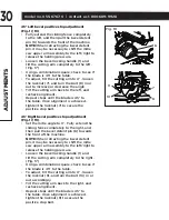
33.9° Left and right bevel adjustment (Fig. 20)
• Set the mitre angle to 0°. Fully extend both
sliding fences.
• Loosen the bevel locking handle, and tilt
cutting arm to the 33.9° right bevel positive
stop by pushing in on the bevel detent
pin (6) towards the rear of the machine.
• Using a combination square, check to see if
the blade is 33.9° to the table.
• To adjust, turn the hex screw (11) in or out
with a 3 mm wrench until the blade is 33.9°
to the table.
• Repeat the above steps and turn the
hex screw (12) for the 33.9° left bevel
adjustment.
MITRE SCALE (Fig. 21)
The sliding compound mitre saw scale can
be easily read, showing mitre angles from 0°
to 50° to the left, and 0° to 50° to the right.
The mitre saw table has positive stops at the
most common angle settings: 0°, 15°, 22.5°,
31.6°, and 45°. These positive stops position
the blade at the desired angle quickly and
accurately. Follow the process below for the
quickest and most accurate adjustments.
Adjusting mitre angles:
• Lift the quick-cam mitre locking lever (1) to
unlock the table.
• Move the turntable while lifting the positive
mitre stop locking lever (2) to align
the indicator (3) to the desired degree
measurement.
• Lock the table into position by pressing
down on the quick-cam mitre locking
lever (1).
Mitre angle pointer adjustment:
• Move the table to the 0° positive stop.
• Loosen the screw (4) that holds the
indicator with a star-head screwdriver.
• Adjust the indicator (3) to the 0° mark and
retighten the screw.
AD
JUS
TMENT
S
Fig. 20
11
12
6
Fig. 21
1
2
3
4


