background image

CAUTION:


YOU NEED A POWER POINT ON THE WALL, SO THAT YOU CAN PLUG IN THE 
FAN. 

NO  POWER  POINT  SHALL  BE  LOCATED  IMMEDIATELY  ABOVE  THE 

HEATER.  IF  ANY  ELECTRICAL  WORK  IS  REQUIRED,  IT  MUST  BE  CARRIED 
OUT BY A LICENSED ELECTRICIAN. IN SOME REGIONS POWER POINTS ARE 
NOT PERMISSIBLE WITHIN THE FLOOR PROTECTOR AREA, PLEASE CHECK 
WITH YOUR LOCAL AUTHORITY.


FAN BOX INSTALLATION OF : 


AUS MODELS 

-

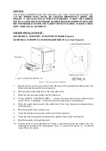
 R5000PED / R12000 PED VERSION (Figure1) 


NZ MODELS 

-

 R5000PED & R10000 MACKENZIE (Rural only) (Figure1)


Figure 1. Pedestal version installation


1.


Break out the ‘knock out’ part on the left face of the pedestal (looking from the 
front) to allow the switch to be inserted. 


2.


Remove the sharp tabs left in the hole with a file. 


3.


Stick the fan operation label next to this hole.


4.


Fit  the  EARTH  TAB  RIVET  BN11    ...inside  the  right  bend  at  the  bottom  hole 
size 5.2.mm  if supplied . (This may have already done in the factory).


5.


Stick the earth decal next to the earth tab. (This may have been already done 
in the factory). 


6.


Remove switch from wiring loom.


7.


Feed the wiring loom up the cavity next to the ash box.


8.


Feed the end through the knockout fan switch hole, shown in Detail A.


9.


Refit the switch to the wiring loom.


10.


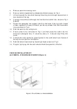
Ensure wires to be connected in Figure 2, and then press  the switch into the 
rectangular  knocked  off  rectangular  hole,  ‘II’  should  be  above  ‘0’.  It  should 
snap firmly into place.


Summary of Contents for R5000 WOOD FIRE

Page 1: ...AU MODELS R5000 PED R5000 LEG R5000 WOOD STACKER R12000 NZ MODELS R5000 PED R5000 LEG R10000 MACKENZIE Rural Only INSTRUCTION FOR FAN INSTALLATION 583271 15 10 2015 ...

Page 2: ...tal looking from the front to allow the switch to be inserted 2 Remove the sharp tabs left in the hole with a file 3 Stick the fan operation label next to this hole 4 Fit the EARTH TAB RIVET BN11 inside the right bend at the bottom hole size 5 2 mm if supplied This may have already done in the factory 5 Stick the earth decal next to the earth tab This may have been already done in the factory 6 Re...

Page 3: ... and test the operation of the fan FAN BOX INSTALLATION OF AUS MODEL R5000 LEG NZ MODEL R5000LEG Figure 3 1 Break out the knock out part on the left side of the leg looking from the front to allow the switch to be inserted 2 Remove the sharp tabs left in the hole with a file 3 Stick the fan operation decal next to this hole Remove the rear brace from the back of the heater as shown in Figure 3 and...

Page 4: ...op screws first then the bottom ones as shown in Fig 3 10 Refit the switch to the wiring loom 11 Ensure wires to be connected in Fig 2 and then press the switch into the knockout rectangular hole II should be above 0 It should snap firmly into place 12 Connect the loose earth wire green yellow to the earth tab at rear channel of the leg this is a push on connection 13 Refit the bottom heat shield ...

Page 5: ...itch bracket and break out the knock out part on the front left side Detail C to allow the fan switch to be inserted 3 Remove the sharp tabs left in the hole with a file 4 Stick the fan operation decal under the switch bracket as shown in figure 6 Figure 5 Wood Stacker Wiring Details ...

Page 6: ...8 Refit the switch to the wiring loom 9 Ensure switch wires are connected as shown in Fig 2 and then press the switch into the knockout rectangular hole II should be above 0 It should snap firmly into place 10 Screw switch bracket in place Endure all cables are tucked properly as shown in Fig 5 i e gap between side panel and the inner side panel 11 Connect the loose earth wire green to the rivet t...

Page 7: ...Figure 7 Circuit Diagram Revision B After Nov 2013 II O I ...

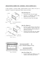
Page 8: ...e 2 x M6 nuts from the back of the air deflector remove bolts and spacers from front hold air deflector in place as you do this 2 Remove the Airslide from the heater and discard this part marked 983221 Figure 10 Step three Step Three Figure 10 1 Discard Airslide part 983221 air and replace it with Airslide part 983278 In New Zealand a special Airslide marked 983278 must be fitted if the fan is ins...

Page 9: ... Air slide 983278 to the front of the heater 2 Refit 2 spacers and 2 x M6X50 bolts back to the top front of the heater 3 Tighten the 2 x M6 nuts to the back of the air deflector to secure all the parts together Figure 12 Step five Step Five Figure 12 1 Refit the louver to the top of the heater using the 2 x M6X10 screws ...

Page 10: ...E A YEAR REMOVING IT TO CLEAN DUST AND LINT FROM THE IMPELLER FIRST UNPLUG THE MAINS LEAD FROM THE POWER POINT REMOVE THE FAN BY UNDOING THE 4 SCREWS HOLDING IT INPOSITION CLEAN THE IMPELLER BLADES CAREFULLY BY BLOWING OR VACUUMING DO NOT APPLY FORCE TO THE IMPELLERS REINISTALL THE FAN OPERATING HINTS FOR CLEAN BURNING AND BEST EFFICIENCY SWITCH OFF THE CIRCULATING FAN WHEN THE FIRE IS BURNING AT ...

Reviews: