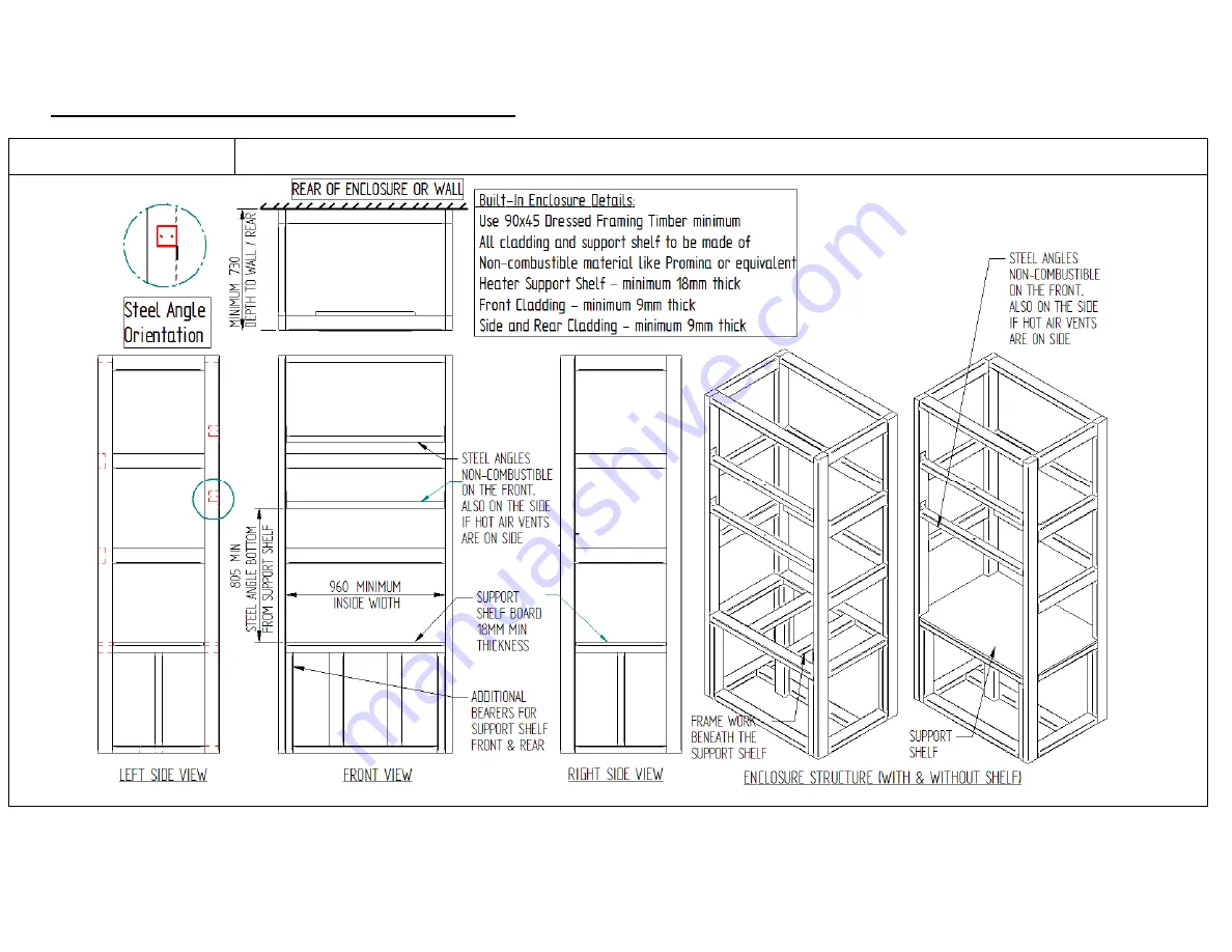
5.0 Installation Procedure for Inverell / I7000 burner
5.1 Built-in Framing
-
DO NOT FIX CLADDING UNTILL FIRE, DUCTINGS AND VENTS ARE FULLY INSTALLED.
Page | 9
Page 1: ...FUTURE REFERENCE Manufactured in New Zealand by GLEN DIMPLEX NEW ZEALAND LIMITED P O Box 58473 Botany Manukau 2163 Ph 0800 666 2824 Fax 09 274 8472 Email sales glendimplex co nz Web www glendimplex co...
Page 2: ...PECIFICATIONS 5 3 0 WORKING PRINCIPLE OF INVERELL I7000 6 4 0 LOCATION OTHER IMPORTANT CONSIDERATIONS 7 5 0 INSTALLATION PROCEDURE FOR INVERELL I7000 9 5 1 BUILT IN FRAMING 9 5 1 1 MINIMUM CLEARANCES...
Page 3: ...s are heavy and tall in size with a total weight of 190 kg Single person handling could cause injury hence Masport recommends suitable handling equipment or two persons while handling both outside and...
Page 4: ...action is considered the manufacturer should be consulted in the first instance Inverell I7000 burner and flue system must be serviced at least once a year or more frequently depending upon usage 1 5...
Page 5: ...along with the flexible ducting fitted to its outer casing The ducting is then vented into the living room or adjacent room In both Australia and New Zealand Inverell I7000 has been tested to and com...
Page 6: ...es around this superhot firebox absorbs heat energy from its outer surfaces and becomes hot to a significant level This hot air rises and exist the zero clearance cabinet through two circular ports lo...
Page 7: ...stalled at an elevated height floor protector requirement depends upon the elevation of fire above ground Support shelf can be maximum up to height of 670mm above the ground Floor protector For an ele...
Page 8: ...be minimum 18 mm thick non combustible material like Promina or equivalent For front side faces of built in cavity use minimum 9 mm thick non combustible material like Promina or equivalent For front...
Page 9: ...5 0 Installation Procedure for Inverell I7000 burner 5 1 Built in Framing DO NOT FIX CLADDING UNTILL FIRE DUCTINGS AND VENTS ARE FULLY INSTALLED Page 9...
Page 10: ...5 1 1 Minimum clearances of built in enclosure to combustibles Page 10...
Page 11: ...by lifting and tilting from the hinge block Keep it away in safe place Take out carton box and keep its contents in safe place Take out 2 x semi rigid Aluminium ducts Remove 4x taptite screws two on...
Page 12: ...lize the entire fire horizontally within the built in cavity Simultaneously using piece of non combustible front cladding material as a gauge position the flanges of fascia forward out of cavity face...
Page 13: ...utout on front side and rear of the built in cavity for air inlets and outlets Air inlet holes need to be minimum 26000 mm2 open area each on side and rear of cavity approx 50mm above support shelf Us...
Page 14: ...ng front or side of the cavity Place the template on the front cladding mark and cut required cutout Use 2x self tapping screw and attach template to front cladding on two sides Drill four dia 4 5 top...
Page 15: ...ed by flue manufacturer Top of the built in cavity or chimney chase must be ventilated either using 300mm dia additional casing or side vent at the top of cavity To begin fix the ZC flue kit adaptor u...
Page 16: ...5 7 Floor Protector Use diagram below to install required floor protection Page 16...
Page 17: ...ring handing and installation of the fire For operations maintenance trouble shooting and warranty terms use Owner s Manual supplied along with the fire Important For any installation variations other...