background image

Masport PG33 Gas Inbuilt

29

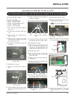
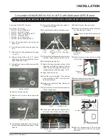
Conversion Kit #436-967 for NG to ULPG

THIS  CONVERSION  MUST  BE  DONE  BY  A  QUALIFIED  GAS  FITTER  IF  IN  DOUBT  DO  NOT  DO  THIS  CONVERSION !!

Burner Orifice

Conversion Kit 436-967 Contains:

Qty. Part #

Description

1 904-575

Burner Orifice #55

1 918-273

Red "ULPG" label

2 918-272

Label "Converted to ULPG"

1 918-339

Instruction Sheet

1 910-920

ULPG Pilot Orifice

1) Shut off the gas supply and unplug the

power cord.

2) Carefully remove the glass, logs and lava

rock.

3) Remove burner. See important note on

page 11 and 18.

4) Remove burner orifice with a 1/2" wrench

and discard. Use a wrench to hold on to the
elbow behind the orifice.

5) Reinstall new burner orifice stamped #55

and tighten.

15) Stick the conversion label  "This unit has

been converted to ULPG" over top of the
serial number decal.

16) Replace the yellow "NG" label with the red

"ULPG" label.

Jumper

6) Remove the rear log tray.

7) Remove the 2 screws which secure the

pilot.

Rear Log Tray

9) Remove the NG pilot orifice and replace it

with the ULPG orifice.

10) Re-install the pilot tube to the pilot assembly.

Pilot

Assembly

Pilot

Orifice

Pilot

Extrusion

Tube

Pilot

Tube

13) Adjust the burner aeration setting to fully

open and re-install the original with the
ULPG burner OR maintain minimum vent
configurations as outlined on page 11 or 18.

14) Open the bottom louvre.

11) Re-install the pilot assembly over the pilot

extrusion tube and secure it with 2 screws.

12) Re-install the rear log tray.

INSTALLATION

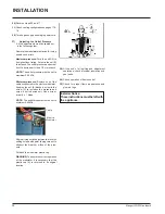
23) Stick the conversion label  "This unit has

been converted to ULPG" on the control box
cover.

17) Remove the screw from  the module and

pull off the module cover.

18) Pull out the 2 orange wires attached to the

valve, and the connector from the module.

screw

module cover

connector

orange connector

wires

19) Carefully pull out the control box.

20) Remove the heat sheild from the control box

by removing the 2 screws.

NOTE: The control box is held in place with
velcro.

21) Remove the control  box cover  by  undoing

the 3 screws.  Maneuver through  antenna.

22) Remove the jumper using a plier.

control box

heat sheild

Control Box

Cover

Antenna

Jumper Location

8) Lift the pilot assembly and remove the pilot

tube from the pilot assembly using a 11mm
wrench.

Summary of Contents for FireGenie PG33-LPG

Page 1: ...vicinity of this or any other appliance Installation and service must be performed by an authorised installer service agency or the gas supplier FORYOURSAFETY What to do if you smell gas Do not try to light any appli ance Do not touch any electrical switch do not use any phone in your building Immediately call your gas supplierfromaneighbour s phone Follow the gas sup plier sinstructions If you ca...

Page 2: ...with all the warmth and charm of a wood fireplace The model PG33 has been approved by the Australian Gas Association for both safety and efficiency As it also bears our own mark it promises to provide you with economy comfort and security for many trouble free years to follow Please take a moment now to acquaint yourself with these instructions and the many features of your Masport Fireplace ...

Page 3: ... Gas Stove 6 Clearances 7 CombustibleMantelClearances 7 MantelLegClearances 7 FramingandFinishing 8 Unit Assembly Prior to Installation 9 FlueingIntroduction 9 ExteriorFlueTerminationLocations 10 Flueing Masport Direct Flue System Flex HorizontalTerminationsonly 11 Flueing Installation of Masport Direct Flue System Flex 12 Flueing Simpson Dura Flue System 13 SimpsonDura FlueComponentsList 14 Fluei...

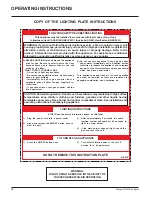
Page 4: ...label that accompanies each PG33 Gas Fireplace We have printed a copy of the contents here for your review DATA BADGE NOTE Masport units are constantly being improved Check the label on the unit and if there is a difference the label on the unit is the correct one ...

Page 5: ...rom burning wood or gas could contain chemicals known to the State of California to cause cancer birth defects or other reproductive harm GENERAL SAFETY INFORMATION 1 The appliance shall be installed in accord ance with the manufacturer s installation instructions localgasfittingregulations mu nicipal building codes water supply regu lations electrical wiring regulations with AG 601 AGA gas instal...

Page 6: ...for your stove ensure that the clearances outlined on this page are met 2 Provide adequate clearances for servicing 3 The appliance must be installed on a flat solid continuous surface e g wood met al concrete This may be the floor or raised up on a platform to enhance its visual impact If the appliance is going to be in stalled on carpeting combustible linoleum tile or other combustible material ...

Page 7: ...ances unless otherwise stated A major cause of chimney related fires is failure to maintain required clearances air space to combustible materials It is of the greatest importance that this fire place and flue system be installed only in accordance with these instructions Clearance to Combustibles from Back 0 0mm Side 0 0mm Floor 0 0mm NOTE The minimum floor clearance must be maintained from the t...

Page 8: ...age 7 1 Determine the total thickness of facing material e g drywall plus ceramic tiles to allow the finished surface to be flush with the front of the unit Total facing thickness canvaryfrom1 2 13mm to1 1 4 32mm thick 6 Use steel studs for framing where the 1 1 2 38mm clearance from the flue to combustiblematerialcannotbemaintained 2 Frame in the enclosure for the unit with framing material Verti...

Page 9: ...Support using the 3 supplied screws into the three pre punched screw holes on the top front of the unit Adjust support to desired facing material depth 2 MountSideNailingStripusingthe3supplied screws into the three pre punched screw holes at the front sides of the unit Adjust support to desired facing material thick ness UNIT ASSEMBLY PRIOR TO INSTALLATION INSTALLATION FLUEING INTRODUCTION The PG3...

Page 10: ...inlet or any other opening into a building with the exception of sub floor ventilation see also Note I Appliances up to 150 MJ h input 500 Appliances over 150 MJ h input 1500 k Vertically below an openable window door or non mechanical air inlet or any other opening into a building with the exception of sub floor ventilation see also Note I see table below Clearance k in mm Space Heaters All Other...

Page 11: ...a flexible liner 2 ft length 2 4 dia flexible liner 2 ft length 3 spring spacers 3 4 thimble 2 5 AstroCap termination cap 1 6 screws 12 7 tube of Mill Pac 1 8 plated screws 8 9 screws 8 x 1 1 2 drill point stainless steel 4 Alternate Horizontal Termination Caps Wherever necessary due to exter nal location of cap the AstroCap can be replaced with the FPI Riser Flue Termination Cap or the Dura Vent ...

Page 12: ...mblybyapplyingMill Pac to the 4 100mm inner collar of the terminationand slippingthe4 100mm liner over it at least 1 3 8 35mm Fasten with the 3 screws drilling pilot holes will make this easier Apply Mill Pac or high temper ature silicone to the 6 7 8 175mm flex pipe and slip it over the 6 7 8 outer collar of the flue terminal at least 1 3 8 35mm and fasten with the 3 screws 4 Separate the 2 halve...

Page 13: ...to suit wall thickness see chart For siding other than vinyl furring strips may be used instead of the vinyl siding standoff to create a level surface to mount the flue terminal The Terminal must not be recessed into siding If a Vinyl Siding Standoff is required it must be used with vinyl siding measure to outside surface of wall without siding and add 2 inches The Masport AstroCapTM is certified ...

Page 14: ...90BG 90O Elbow Swivel Black 991 High Wind Termination Cap Vertical 980 Vertical Termination Cap 984 Horizontal Square Termination Cap 985 Horizontal Square High Wind TerminationCap 982 Snorkel 14 Rise Termination Cap 981 Snorkel 36 Rise Termination Cap 940 Wall Thimble Support Box 941 Cathedral Ceiling Support Box 3951 Brass Trim for Wall Thimble Ceiling Support 963 Firestop Spacer 943 Flashing 0 ...

Page 15: ... Note Must use optional flue adapter when using Simpson Dura Vent pipe Part 510 994 FLUEING ARRANGEMENTS VERTICAL TERMINATIONS SIMPSON DURA FLUE DIRECT FLUE GS SYSTEM NG LPG ULPG The shaded area in the diagram shows all allowable combinations of straight vertical and offset to vertical terminations using one 90o elbow with Simpson Dura Flue Direct Flue GS flue systems for NG LPG and ULPG ...

Page 16: ...rea in the diagram shows all allowable combinations of straight vertical and offset to vertical terminations with Simpson Dura Flue Direct Flue GS flue systems for LPG ULPG and NG Maximum two 45o elbows allowed Flue must be supported at offsets Firestops are required at each floor level and whenever passing through a wall Maintain clearances to combustibles INSTALLATION ...

Page 17: ...zontal flue must be supported every 3 feet Firestops are required at each floor level and whenever passing through a wall A flue guard should be used whenever the termination is lower than the specified minimum or as per local codes Note Masport Direct Flue System Flex is only approved for horizontal ter minations INSTALLATION Minimum Simpson Dura Flue Center Line Minimum Flex Kit Center Line Impo...

Page 18: ...adapter Part 510 994 when using Simpson Dura Vent pipe Refer to page 13 Maintain clearances to combustibles Horizontal flue must be supported every 3 feet Firestops are required at each floor level and whenever passing through a wall A flue guard should be used whenever the termination is lower than the specified minimum or as per local codes Note Masport Direct Flue System Flex is only approved f...

Page 19: ... min of 11 feet total vertical and max 9 feet total horizontal Please note min 1 foot between 90o elbows is required With these options maxi mum total pipe length is 30 feet with minimum of 6 feet total vertical and maximum 8 feet total horizontal Please note minimum 1 foot between 90o elbows is required INSTALLATION One 90o elbow Two 45o elbows One 90o elbow Two 45o elbows One 90o elbow Two 45o e...

Page 20: ...B 0 6m 1 5m 0 9m C 0 9m 1 8m 1 2m D 1 2m 2 1m 1 5m E 1 5m 2 4m 1 8m Vertical Flueing with Two 2 90o Elbows With these options max total pipe length is 30 feet with min of 6 feet total vertical and max 8 feet total horizontal Please note min 1 foot between 90o elbows is re quired Option H H1 V Max Min A 0 6m 0 6m B 0 9m 0 9m C 1 2m 1 2m D 1 5m 1 5m E 1 8m 1 8m With these options max total pipelengt...

Page 21: ...d max 8 feet total horizon tal Please note min 1 foot between 90o elbows is re quired Vertical Flueing with Three 3 90o Elbows Option H V H H1 V V1 Max Min Max Min A 0 3m 0 3m 0 9m 0 9m B 0 6m 0 6m 1 2m 1 5m C 0 9m 0 9m 1 5m 2 1m D 1 2m 1 2m 1 8m 2 7m E 1 5m 1 5m 2 1m 3 3m With these options max total pipe length is 30 feet with min of 11 feet total vertical and max 7 feet total horizontal Please ...

Page 22: ...Arrangements on next page for minimum and maximumheights Masonry chimneys may take various contours which the flexible liner will accommodate However keep the flexible liner as straight as possible avoid unnecessary bending The Air Intake pipe must be attached to the inlet air collar of the termination cap Required Parts Part Description 946 529 Co linear DV Vertical TerminationCap 948 305 3 Flex ...

Page 23: ...t 23 Flueing Arrangements Vertical Terminations with Co linear Flex System for both Residential Manufactured Homes into Masonry Fireplaces The shaded area in the diagrams show the allowable vertical terminations INSTALLATION ...

Page 24: ... want to adjust the location of the unit Rough in the gas preferably on the right side of the unit andtheelectrical junctionblockisontheleft side on the left 2 Direct Flue pipe and fittings are designed with special twist lock connections to con nect the flueing system to the appliance flue outlet A twist lock appliance adaptor is an available option that must be used in con junction with the Simp...

Page 25: ...meets theminimumheightrequirementsspecifiedin Dia 4 or local codes Note that for steep roof pitches theverticalheightmustbeincreased A poor draft or down drafting can result from high wind conditions near big trees or adjoin ing roof lines in these cases increasing the flue height may solve the problem 7 Ensure flue is vertical and secure the base of the flashing to the roof with roofing rails sli...

Page 26: ...valve is in the OFF position 2 Loosen the IN 3 and or OUT 4 pressure tap s turning counterclockwise with a 1 8 wide flat screwdriver 3 Attach manometer to IN and or OUT pressure tap s using a 5 16 ID hose 4 Seal and or check the pilot outlet 8 5 The pressure check should be carried out with the unit burning and the setting should be within the limits specified on the safety label 6 When finished r...

Page 27: ...ule cover 18 Pull out the 2 orange wires attached to the valve and the connector from the module 6 Remove the rear log tray 7 Remove the 2 screws which secure the pilot Rear Log Tray 9 Remove the NG pilot orifice and replace it with the LPG orifice Pilot Assembly Pilot Orifice Pilot Extrusion Tube Pilot Tube 13 Adjust the burner aeration setting to 12 7 mm and re install the burner 14 Open the bot...

Page 28: ...e outlet pressure must be set to maximum2 61kPa Minimum pressure Remove one of the cables connected to the electric modulator Keeping the nut B blocked screw in the screw C to increase the pressure and screw it out to decrease it Use a screw driver 6 x 1 blade NOTE The outlet pressure must be set to minimum0 70kPa After carrying out all adjustments block the setting screws with paint taking care n...

Page 29: ...with the ULPG orifice 10 Re installthepilottubetothepilotassembly Pilot Assembly Pilot Orifice Pilot Extrusion Tube Pilot Tube 13 Adjust the burner aeration setting to fully open and re install the original with the ULPG burner OR maintain minimum vent configurations as outlined on page 11 or 18 14 Open the bottom louvre 11 Re install the pilot assembly over the pilot extrusion tube and secure it ...

Page 30: ...ssure Remove one of the cables connected to the electric modulator Keeping the nut B blocked screw in the screw C to increase the pressure and screw it out to decrease it Use a screw driver 6 x 1 blade NOTE The outlet pressure must be set to minimum0 60kPa After carrying out all adjustments block the setting screws with paint taking care not to obstruct the breather orifice of the pres sure Put ba...

Page 31: ...of the serial number decal 16 Replace the yellow NG label with the red ULPG label Jumper 9 Remove the NG pilot orifice and replace it with the ULPG orifice 10 Re install the pilot tube to the pilot assem bly Pilot Assembly Pilot Orifice Pilot Extrusion Tube Pilot Tube 13 Adjust the burner aeration setting to fully open and re install the original with the ULPG burner OR maintain minimum vent confi...

Page 32: ...ssure Remove one of the cables connected to the electric modulator Keeping the nut B blocked screw in the screw C to increase the pressure and screw it out to decrease it Use a screw driver 6 x 1 blade NOTE The outlet pressure must be set to minimum0 60kPa After carrying out all adjustments block the setting screws with paint taking care not to obstruct the breather orifice of the pres sure Put ba...

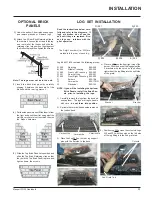
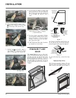
Page 33: ...nd unwrap them The logs are fragile handle with care do not force into position 2 Sprinkle the vermiculite and embers around the firebox base Notch Bracket Bracket 250 254 Vermiculite Vermiculite Vermiculite 250 254 The 3 digit numbers i e 250 are molded into the rear of each log Read the instructions below care fully and refer to the diagrams If logs are broken do not use the unit until they are ...

Page 34: ...m piece then attach trim to the top and bottom of Flush door 5th Grate Tab 6 Place the bottom left front edge of Log 251 against the left edge of the burner tray and rest the log on the cutout on Log 253 7 Position Log 252 across the cutouts in Logs 254 and 253 The notch in the bottom right end fitting against the 5th grate tab 8 Pull off ember size pieces of rockwool and gently place them on the ...

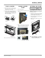
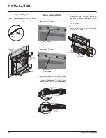
Page 35: ... Install the top louver by sliding the two bracket clips into the brackets located un derneath the top of the firebox 2 Install the bottom louver by folding the lou ver down and then sliding the Bottom Lou ver bracket down onto the 2 pins on the base of the unit dia 1 Secure with 1 screw as per diagram 2 Note Top and bottom louvers are different Note If any maintenance etc must be done in the fire...

Page 36: ...a small gap between faceplate bot tom and louver top Bay Louver Top Heat Shield 4 Install bottom louver by sliding the two bracket clips into the brackets located un derneath the bay door Secure with 1 screw into each Bottom Louver Mounting Bracket as per diagram below Use the bottom hole in the bracket 5 Slide the valve extension knobs onto the valve knobs Match the correct ext knob with the valv...

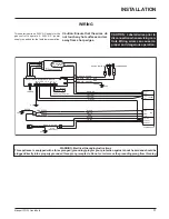
Page 37: ...nged grounding plug for your protection against shock hazard and should be plugged directly into a properly grounded three prong receptacle Do not cut or remove the grounding prong from this plug GREEN BROWN ACTIVE BLUE NEUTRAL HIGH SPEED LOW SPEED FAN VIOLET BLUE BROWN WHITE RED BLACK FLAME SENSOR PILOT SPARK IGNITOR RED 1 2 3 4 5 6 7 8 9 10 11 12 SIT 201 IGNITION CONTROL MODULE BLACK BLACK RESET...

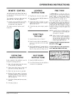
Page 38: ... if any part has been under water Immediately call a qualified service technician to inspect the appliance and to replace any part of the control system and any gas control which has been under water This appliance needs fresh air for safe operation and must be installed so there are provisions for adequate combustion and ventilation air LIGHTINGINSTRUCTIONS TO TURN OFF GAS APPLIANCE This applianc...

Page 39: ...ease the ON OFF button once to start the unit 3 After approximately 3 seconds the spark ignition system will spark for 40 seconds to light the main burner 4 If the main burner does not light reset the unit RESETTING THE UNIT 1 Open the bottom louvre of the unit 2 Press the reset button for approximately 3 seconds It is located on the unit s control panel once 3 Wait for approximately 3 seconds and...

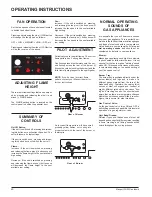
Page 40: ...hat can be adjust ed by pressing and releasing the plus and minus FLAME button The FLAME setting button is located on the control panel in behind the pedestal door SUMMARY OF CONTROLS On Off Button If the unit is switched off pressing and releas ing this button once will switch the unit on The unit will resume its last settings If the unit is switched on pressing and releas ing this button once wi...

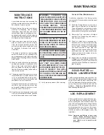
Page 41: ...agile and easily damaged 2 Clean glass never when unit is hot ap pliance louvres and door with a damp cloth Never use an abrasive cleaner The gold louvres and optional gold door may be scratched if abrasives are used to clean them The heater is finished in a heat resistant paint and should only be refinished with heat resistant paint not with wall paint Masport uses StoveBright Paint Metallic Blac...

Page 42: ...e appliance with the glass panels removed cracked or broken Re placement of the glass panels should be done by a licensed or qualified service person Caution Wear gloves when remov ing damaged or broken glass GLASS GASKET If the glass gasket requires replacement use 5 8 flat glass gasket for the Bay Front Part 936 243 and a tadpole glass gasket for the Flush Front Part 936 155 DOOR GLASS Your Masp...

Page 43: ...ly pull out the ECS box 6 Remove the electric cover by undoing the 2 screws pull out the grommet and the harness 7 Unplug the black wire from the resister 8 Carefully slide the fan to the front left side of the unit 9 Remove the screw which holds the ground wire and disconnect all electrical connectors that are attached to the fan ECS Box 6 Pin Molex Connector 10 Pull out the fan 11 Reverse steps ...

Page 44: ...rews Rear Log Stand 7 Disconnect the inlet gas line 8 Remove the 10 Philips screws which secure the valve tray assembly 9 Unplug the 2 orange wires from the Gas Pressure Electric Modulator 10 Unplug the 5 pin Molex Connector from the valve 11 Unplug the ignitor and flame cables from the module and then lift the entire valve tray assembly out 5 Pin Molex Connector Module 2 Orange Wires Ignitor Cabl...

Page 45: ...ne Brown 432 904 Brick Panel Set Herringbone Red 33 Brick Panel Rear 34 Brick Panel Left Side 35 Brick Panel Right Side 36 Brick Panel Top 37 430 056 Brick Clip Top 38 430 057 Brick Clip Bottom 432 945 Herringbone Brick Panel Set Optional 902 359 Brick Panel Rear 902 358 Brick Panel Left Side 902 360 Brick Panel Right Side 902 361 Brick Panel Top 946 556 Optional Heat Wave Duct Kit 89 946 004 Junc...

Page 46: ...0 915 Pilot Assembly NG 904 568 Orifice 44 NG 904 163 Orifice 54 LPG 904 575 Orifice 55 ULPG 936 170 Orifice Gasket 67 PilotHolder 68 W840470 Pilot Assembly Gasket 79 433 525 Burner Assy NG LPG 82 433 024 Burner Grate Assembly NG LPG 83 Rear Log Support Bracket NG LPG 85 431 930 Log Set 86 430 097 Air Deflector Left 87 433 018 Air Deflector Right Not available as a replacement part PARTS LIST ...

Page 47: ...162 Front Deflector 134 Flush Louver Assy Bottom 433 538 Flush Door Assembly Complete 135 940 088 P Glass Flush 137 904 691 U Clip 139 936 155 Glass Gasket Tadpole 140 948 042 Spring Hinge Black 430 940 Finishing Trim Set Black Option 430 942 Finishing Trim Set Brass Option 157 Finishing Trim Left 159 FinishingTrimRight 158 Finishing Trim Top 431 943 Double Screen Door Complete Option 171 Door Fra...

Page 48: ...own 120 400 189 Glass Retainer 432 956 Bay Door Trim set Gold 432 954 Bay Door Trim set Brass 432 958 Bay Door Trim set Brushed Steel 123 Bay Door Trim each Black 430 932 Bay Louvers set Gold Black 430 934 Bay Louvers set Brass Black 430 936 Bay Louvers set Black 430 937 Bay Louvers set Steel Black 125 Bay Louver Assy Top 433 026 Bay Door Deflector 126 Bay Louver Assy Bottom 129 948 042 Hinge 130 ...

Page 49: ...___________________________________________ ______________________________________________________ _______________________________________________________________ ___________________________________________________________ __________________________________________________________ ____________________________________________________________ _________________________________________________________...

Page 50: ...___________________________________________ ______________________________________________________ _______________________________________________________________ ___________________________________________________________ __________________________________________________________ ____________________________________________________________ _________________________________________________________...

Page 51: ...Service Agent This Express Warranty Does Not Cover 1 Defects malfunctions or failures caused by incorrect installation normal wear and tear misuse neglect accidental damage or failure to follow the fuel selection product operating and maintenance instructions or resulting from installations repairs or modifications to the equipment carried out by unauthorised persons 2 Defects malfunctions or fail...

Page 52: ...Printed in Canada Copyright 2005 FPI Fireplace Products International Ltd All rights reserved ...

Reviews: