background image

23 


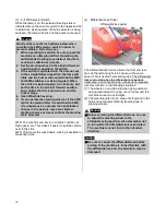
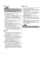
 How to Feed Water


Warning 

 Never feed water directly from a drinking water 

source or any lake or pond used for aquatic 
farming. 

 
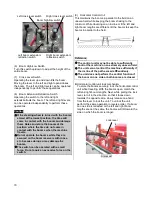
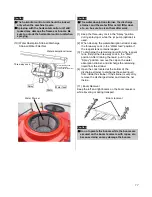
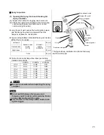
(1)  Move the three-way cock in the 

“Spray” position 

and add the required amount of water in the 
reagent tank.   

* If no water supply facility is available, a spray pump 

water feeding hose or a jet pump (optional) would be 
useful. 

 
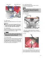
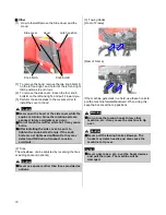
(2)  How to Operate the Spray Pump Water Feeding 

Hose 


[1]  Connect the spray pump water feeding hose. 


Spray pump water feeding hose 

 
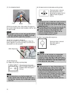
[2]  Open the lid of the reagent tank. 
[3]  Throw the strainer end of the spray pump water 

feeding hose into the water source.   

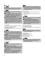
[4]  Press the spray pump switch and confirm that the 

water inside the reagent tank is circulating. At this 
point, set the throttle lever in the idling position.   

[5]  Set the three-way cock in the 

“Water feed” position. 

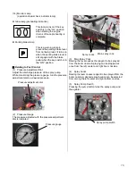
[6]  Once the water feeding begins, pull the throttle 

lever fully to set the engine to a normal speed.   

 
[7]  Using the reagent tank water gauge as the 

guideline, when the tank is filled with the required 
amount of water for spraying, return the throttle 
lever to the idling position, set the three-way cock 
to the 

“Spray” position, and then press the spray 

pump button to stop the water feeding. 

[8]  Disconnect the spray pump water feeding hose. 
 

Caution 

 Be sure to add priming water when feeding 

water. If the idling lasts too long while feeding 
water, the spray pump may be damaged. 


Supplement 

 Use all of the reagent in the tank first before 

adding water. When feeding water when the 
reagent tank still has residual liquid, use a jet 
pump (optional) or another water feeding 
device. 

 Exercise caution as a small amount of residual 

water will come out from the pipe when 
disconnecting the spray pump water feeding 
hose. 

 
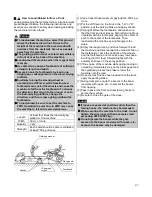
(3)  How to Operate the Jet Pump   
[1]  Prime around 20 L of water into the reagent tank. 
[2]  Connect the pipe from the jet pump and open the 

cock. 

[3]  Throw the strainer end of the jet pump into the 

water source and insert the opposite end to the 
water inlet of the reagent tank.   

[4]  Close the spray cock fully.   
[5]  Put the throttle lever in the idling position and press 

the spray pump switch. 

[6]  Pull the throttle lever and set the engine to the 

medium speed. 

[7]  Confirm that all spray cocks are closed, and raise 

the main spray cock lever to increase the pressure. 

[8]  Operate the pressure adjustment dial to set the 

spray pressure to 2 to 2.5 MPa. 

[9]  Once the required amount for spraying has been 

added, close the jet pump cock. 

[10] Lower the main spray cock lever, return the throttle 

lever to the idling position, press the spray pump 
switch to stop the pump, and disconnect the jet 
pump. 


Three-way cock 

Water feeding hose 
connecting joint   
(also used for the drain) 

Spray 

Drain 

Water feed 

Summary of Contents for BSA-950LM

Page 1: ...1 Operation Manual Maruyama Boom Sprayer Be sure to read before use BSA 950LM ...

Page 2: ...by using the product outside the foregoing scope of use or accident arising from an unauthorized modification or disassembly Precautions The precautions contained in this manual and warning labels bearing you see on the machine provide important items that may cause injury if neglected Read these precautions and labels carefully and be sure to follow the instructions In this Operation Manual parti...

Page 3: ... m Pressure Pa Pascal 0 98 MPa 10 kgf cm2 9 8 Pa 1 mmH2O kgf cm2 mmH2O Work ratio drive power W watt 735 5 W 1 PS 9 8 W 1 kgf m s PS kgf m s Notes 1 a and ha may be used to indicate land areas 2 The number of revolutions per unit time is indicated as rotational speed not as revolutions Specifications In this Operation Manual products of different specifications are indicted as follows Confirm the ...

Page 4: ...o suddenly move resulting in an accident 3 Keep non operators especially children away from the area where pest control work is performed Failure to do so may lead to an accident 4 Exercise due caution not to pollute water supply systems rivers ponds lakes etc 5 Never refuel near a fire source as it may cause fire Refueling while smoking is strictly prohibited 2 Items to Note before Operation 1 Ca...

Page 5: ...ry dangerous situation 3 Maintain the approach path so that the inclination angle of approach to the field is kept within 15 degrees 6 Loading Unloading to from a Truck Refer to P 1 When loading the machine to a truck empty the reagent tank and drive the machine head in When unloading the machine drive the machine slowly in reverse 2 Use a truck whose payload is 2 000 kg or more 3 Move the machine...

Page 6: ... optional Right boom Steering wheel Seat Reagent tank lid Reagent tank Hood Boom receiver Fuel tank Steps Left boom Floor Auxiliary shift lever 2 4WS selector switch 4WS indication lamp HST lever 2WS indication lamp Work lamp switch optional Fuse box Fuel level gauge ...

Page 7: ...ake lamp Combination switch Brake pedal Differential lock pedal Pressure adjustment dial Water temperature warning lamp Oil pressure lamp Main spray cock Pump button Spray cock Glow lamp Right boom cross lever switch Boom high low switch Right boom extension retraction switch Key switch Hour meter Left boom extension retraction switch Parking brake lever Accelerator pedal ...

Page 8: ...Clutch Dry type single plate type interlocked with the brake pedal Brake also used as parking brake Wet multi disk mechanical type Tires front rear 120 90 26 6PR Air pressure 300 kPa Battery 55B24R Reagent tank capacity L 850 900 max Agitation method Propeller mechanical type Spray pump Name MS1000F Type Lateral quintuple piston type Rotational speed rpm 1250 Water absorption L min 100 Pressure ma...

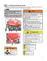
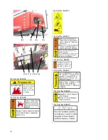
Page 9: ...e labels Warning Constantly remove soiling and mud over the labels so that the information provided on them remains clearly visible Replace damaged warning labels with new ones If a part on which a warning label is attached has been replaced be sure to attach a new label on the new part at the same location 1 Part No 880263 2 Part No 880271 3 Part No 880258 4 Part No 880260 5 Part No 880259 5 1 2 ...

Page 10: ...10 6 Part No 880264 7 Part No 880268 6 Part No 866073 9 Part No 880270 10 Part No 880261 11 Part No 880269 12 Part No 880265 13 Part No 869745 10 11 13 12 6 7 8 9 ...

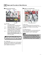
Page 11: ... use the accelerator pedal to adjust the engine speed Relating to Traveling Operation 1 HST Lever Tilt the lever forward from the N position to move forward or tilt it rearward to move in reverse The more you tilt the lever the higher the machine speed becomes 2 Auxiliary Shift Lever There are two shift gears one for high speed and the other for low speed To start the engine put the auxiliary shif...

Page 12: ...ater than anticipated change in the posture may occur Before starting to move or travel confirm the steering state selected 2WS The machine can travel in a stable condition at high speed etc This makes it easier to pull the vehicle over to the side 4WS This steers the rear wheels making it possible to make tight turns 4 Differential Lock Pedal The differential lock device allows the front and rear...

Page 13: ...lease it to run the engine idle It is interlocked with the throttle lever and when the throttle lever is pulled the pedal will be automatically set to the position where it is stepped on 8 Power Steering Wheel This hydraulic steering wheel is used to turn the machine or change its course Caution Avoid static steering turning the steering wheel when the machine is not traveling because it will caus...

Page 14: ...e engine is turning immediately stop the machine in a safe place and stop the engine and contact the Maruyama dealer near you Continuing to travel on the machine despite the lamp remaining on may damage the engine The oil pressure warning lamp does not indicate insufficiency of oil Check the oil amount using the oil level gauge Checking adding engine oil P Water Temperature Warning Lamp This lamp ...

Page 15: ...sure of the spray pump While monitoring the pressure gauge turn the pressure adjustment dial to a desired pressure 2 Pressure Gauge The pressure adjusted with the pressure adjustment dial is indicated 3 Main Spray Cock Raising the lever causes the reagent to be sprayed from the boom nozzle Spraying can be stopped at once from the left center and right boom nozzles 4 Spray Cocks Raising the lever c...

Page 16: ...el to the field on an uneven field while keeping the boom shaking to the minimum While traveling on an incline or if the left and right boom lengths are different tilt the booms to keep the booms in parallel to the field Reference The control unit may not be able to sufficiently control the machine on an extremely uneven field The unit cannot control the machine sufficiently if the incline of the ...

Page 17: ...agent 3 To discharge the remaining liquid from the reagent tank first put the three way cock in the Drain position After draining the liquid put it in the Spray position remove the cap on the water absorption strainer and discharge the remaining liquid from the strainer 4 Open the cock located at the bottom of the discharge strainer to discharge the soiled liquid from inside the strainer If the st...

Page 18: ...b bolts strongly If the knob bolts are not tightened sufficiently they may detach and fall during transport causing accidents 2 Tires The wheelbase can be adjusted by reversing the tires or adding spacers optional Caution Never use spacers other than those provided as options 3 Towing Hooks Front of Frame Rear of Frame If the machine gets stack in a field use these hooks to pull the machine forwar...

Page 19: ...ine and take an appropriate measure If you hear abnormal noise different from what you hear every day stop the engine and investigate the cause If the cause cannot be identified contact your Maruyama dealer 8 Return the throttle lever to the low speed side and warm up the engine for 5 minutes before commencing work Warning Warm up the engine outdoors to prevent exhaust gas poisoning Caution Be sur...

Page 20: ...o Travel Caution Do not carry anyone other than the driver or objects Wear a helmet to ensure safety Exercise due caution and lower the speed when going through a narrow agricultural land or on a road with shoulders Trim weeds to expose the road shoulders Adjust the traveling speed using the HST lever the throttle lever and the accelerator pedal Drive according to the traffic rules even on private...

Page 21: ... of mass 1 Use a truck whose maximum payload is 2 000 kg or more 2 Put the shift lever on the truck in the 1st or R position pull the parking brake and apply chocks 3 Stop right before the footboards and make sure that the front and rear tires on both left and right are in parallel with the footboards aligning the center of each to the center of the footboards Then load unload the machine at a rig...

Page 22: ...d is kept within 15 degrees If the approach path to the field is soft or the inclination angle is 15 degrees or more be sure to use footboards to keep the inclination angle within 15 degrees If the length of the approach path is at least four times the height of the road from the field the inclination angle is within 15 degrees When going over a furrow be sure to approach by orienting the machine ...

Page 23: ...se Caution Be sure to add priming water when feeding water If the idling lasts too long while feeding water the spray pump may be damaged Supplement Use all of the reagent in the tank first before adding water When feeding water when the reagent tank still has residual liquid use a jet pump optional or another water feeding device Exercise caution as a small amount of residual water will come out ...

Page 24: ...h The spray pump will actuate and agitation will start in the reagent tank at the same time 5 Put the reagent in the reagent tank by making sure it does not spill out of the tank and agitate the reagent fully Caution The spray pump and jet agitation are interlocked Once the spray pump stops jet agitation also stops Do not stop the spray pump while reagent remains in the tank because chemical damag...

Page 25: ...3 pcs Table of nozzle discharge flow rates per nozzle Ceramic cone nozzle L min 1 0 MPa 1 5 MPa 2 0 MPa 1 0 0 53 0 66 0 77 1 1 0 60 0 73 0 85 1 2 0 66 0 82 0 96 1 3 0 73 0 89 1 05 1 4 0 78 0 98 1 12 1 5 0 86 1 09 1 28 1 6 0 96 1 20 1 39 Caution Be sure to use water when inspecting the spray condition Caution Do not switch between the two way and three way switch nozzles while spraying Doing so may...

Page 26: ...f the boom sprayer may change In this case the slip factor must be corrected Depending on the state of the field the tire slip factor may vary and the spray speed may deviate in which case the nozzle spray amount must be set according to these different slip factor spray speed For more accurate spraying measure the actual slip factor in the field Rough guide for slip factor 5 General crop field wh...

Page 27: ...27 Nozzle pressure MPa Quick Calculation Diagrams 3 4 1 6 L min must not be exceeded Eco Shower B08 Kirinashi N KA 8R Double nozzle type 1 6 Cone 1 6 1 2 Spray speed km h ...

Page 28: ...pressure when the spray cock fully closed is different from the pressure during spraying adjust the pressure once again to a desired level during spraying 5 Open the booms Extend retract the booms and align the spraying width with the ground 6 Put the auxiliary shift lever in the spray position 7 Open the spray cock and slowly tilt the HST lever in the moving direction until a desired speed is ach...

Page 29: ...c Disposing of such items on land or in river may be punishable by law Periodic Inspection Standards 1 The applicable inspection timing is indicated by 2 The timing of initial inspection is indicated by Inspection item Inspection timing Judgment criterion Start of work Every 6 months Every 12 months Hours Steering operation Steering wheel handle Play looseness rattling 50 Operating feel 50 Rods an...

Page 30: ...iping Looseness of joint and leakage of oil Motor Starting device Degree of pinion meshing Charge device Charge action Battery Fluid level 50 Fully charged 1 260 20 C Fully discharged 1 060 20 C Specific gravity of fluid Electrical wirings Loose and damaged connection parts Main body Ease of starting and abnormality Condition at low speed and during acceleration Exhaust condition Condition of air ...

Page 31: ...ge Exhaust pipe and muffler Looseness and damage of mount Muffler function Machine frame and body Looseness and damage Location where abnormality was found during operation the day before Confirm that the applicable location is free from abnormality Other Lubrication condition at each part of chassis Other items Fuel tank Water absorption strainer Note1 Clean Line strainer Note1 Clean Tank water f...

Page 32: ...AE 90 0 8 L 600 5 Front rear differential oil 1 0 L 6 Spray pump crank case SAE10W 30 API SJ grade or better 0 6 L 100 7 Spray pump cylinder base metal 3 to 5 drips Every 100 hours or every year 8 Boom shaft receiver 2 to 3 drips At start of work At start of work 9 Each wire 10 Boom lift open close shaft Refer to the following Chassis grease Appropriate amount 20 20 11 Radiator LLC 4 9 L 600 Greas...

Page 33: ...tion not to get burned Do not touch any of the parts directly with your hand Oil filter cartridge Replace every 150 hours or after 50 hours initially The oil filter is of cartridge type so remove the entire case with a filter wrench and replace it with a new one After the new oil filter has been assembled operate the engine to check for leakage of oil After the oil change stop the engine after 5 m...

Page 34: ...me manner and then tighten screw B 5 Turn the key switch to ON Operate the solenoid pump for approx 10 seconds in this condition to bleed air trapped between the solenoid pump and engine Caution When bleeding air put clothes underneath and wipe off any spilled fuel Stop the engine during refueling Fuel Filter Clean the fuel filter every 100 hours or so of operation and replace the element every 40...

Page 35: ...Open the drain plug and drain cooling water fully Thereafter clean the inside with tap water until the flushed water no longer contains rust 5 Changing the Transmission Oil Remove the plug on the oil check port and drain plug at the bottom of the transmission and drain oil At this time open the oil filler port also Open the oil check port to bleed air from inside the transmission when adding oil T...

Page 36: ...f oil Approx 0 6 L When to change Initial change 50 hours Periodic change Every 100 hours 9 Greasing Refer to the Oil Change Table P 10 Adjusting the Belt Tension Adjust the belt tension based on the table below Press the center of the belt with the amount of force indicated in the table and adjust to the deflection indicated Drive part Belt type Amount of force to press the center of belt N Defle...

Page 37: ...d level is between UPPER and LOWER If the level is low add distilled water to the UPPER level 2 After distilled water has been added securely tighten the cap 3 Inspect the battery terminals and if loose securely tighten the terminals If white powder is attached to the terminals clean with hot water and tighten the terminals and then apply a small amount of grease on the terminals Caution Do not co...

Page 38: ...entire surface of the inner wire and assemble it back to the original position 15 Inspecting the Rear Axle Stopper Bolts If the machine body tilts significantly when the driver gets on board or gets off request to have the rear axle stopper bolts adjusted at the sales dealer where the machine was purchased 16 Inspecting the Floor Inspect the floor for cracks fissures or any other abnormality If an...

Page 39: ...ge on the parts by naturally dropped boom lift attach the hooks to the boom lift as shown based on the procedure below 1 Close the booms on both sides adjust the boom lift so that it is in a parallel position and store the booms in the boom receivers 2 Stop the engine 3 Latch the hook onto the pipe of the boom lift at two positions on left and right Caution Do not place anything underneath the boo...

Page 40: ...ng Diagram Each arrow in the piping diagram indicates the flow direction of water or reagent Reagent tank Spray pump Pressure adjustment valve Strainer Feed valve Foot valve Cock Drain plug Boom nozzle Jet pump ...

Page 41: ...rom the fuel tank fuel filter and add new fuel Clogged fuel injection nozzle Contact the dealer where you purchased your machine from Clogged fuel filter Contact the dealer where you purchased your machine from Engine related Insufficient engine output Insufficient fuel Inspect the fuel system for entry of air Clogged air cleaner Contact the dealer where you purchased your machine from Insufficien...

Page 42: ...ne from Steering wheel related The steering wheel is heavy Insufficient tire pressure Adjust the pressure to the reference level Hydraulic device malfunction Contact the dealer where you purchased your machine from Steering control is lost Uneven pressures of tires Adjust the pressures of all tires evenly Poor straight rolling property of tire Contact the dealer where you purchased your machine fr...

Page 43: ...etached wire terminal Reconnect and retighten after inspection Faulty hydraulic device Contact the dealer where you purchased your machine from Improper slide condition Loose or disconnected wire terminal Contact the dealer where you purchased your machine from Excessively tight or loose extension retraction chain and wire Contact the dealer where you purchased your machine from Loose mounting wir...

Page 44: ...ISEI CS 04 Harness Slow blow fuse 685844 1 40A Fuse box Fuse 30A 641496 4 Fuse 15A 185012 Fuse 10A 641262 4 Fuse 5A 191738 3 Combination lamp Bulb 595551 3 Glow lamp Bulb 581116 1 Parking brake lamps Bulb 581116 1 Head lights Bulb 2 H3 12V 35W Blinker Bulb 626906 2 12V 15W Spray pump Water absorption valve 027944 5 Piston gasket set 115420 5 Water absorption valve collar 125924 5 Water absorption ...

Page 45: ...failure Explain in detail what happened when such and such was operated in which way in which condition So that it can be used safely this product must be operated correctly and serviced periodically Have your machine inspected and serviced at least once a year by the dealer where you purchased your machine from This servicing is chargeable Supply Period of Spare Parts Spare parts for this product...

Page 46: ... 00 Apr 2015 MARUYAMA MFG CO INC If you have any question or inquiry regarding this product consult first the dealer where you purchased your machine from You can also call the following toll free number from anywhere in Japan Maruyama Support Center Toll free number 0 1 2 0 898 1 1 4 Lines are open from 9 00 to 17 00 excluding Saturday Sunday and public holidays 4 15 Uchikanda 3 Chome Chiyoda Ku ...

Reviews: